Sealed type direct current contactor with high breaking capacity

A DC contactor, sealed technology, used in relays, electromagnetic relays, electromagnetic relay details and other directions, can solve the problems of contact wear, can not be prevented, long arcing time, etc., to reduce wear, improve service life, improve Effects of insulating properties and protective capabilities

Inactive Publication Date: 2016-04-20
SHENZHEN BUSBAR SCI TECH DEV
View PDF6 Cites 5 Cited by
  • Summary
  • Abstract
  • Description
  • Claims
  • Application Information

AI Technical Summary

Problems solved by technology

[0003] The electromagnets of existing DC contactors generally use double-winding coils. Specifically, a pair of auxiliary normally closed contacts is set at the bottom of the housing. The contactor must form a non-sealed structure, and between the small cap and the shell, between the electromagnet, the mounting plate, and the seat plate assembly, the bonding surface between the cap cove

Method used


Image

  • Sealed type direct current contactor with high breaking capacity
  • Sealed type direct current contactor with high breaking capacity

Examples


Embodiment 1

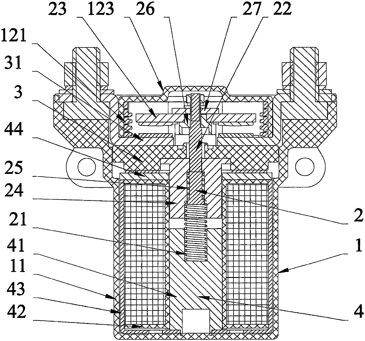
[0044] Attached figure 1 And attached figure 2 As shown, a sealed DC contactor with high breaking capacity. The external structure 1 includes a housing 11 and an arc extinguishing cover 12 .

[0045] The action system 2 includes a reaction force spring 21 , a push rod 22 , a bridge terminal assembly 23 and a moving iron core 24 .

[0046] The contact system 3 comprises a contact assembly 31 .

[0047] The magnetic circuit system 4 includes a static iron core 41 and an electromagnetic coil 42 .

[0048] The reaction force spring 21 and the bridge terminal assembly 23 are installed on the lower end and the upper end of the push rod 22 respectively; the moving iron core 24 is installed inside the electromagnetic coil 42 and connected with the push rod 22 .

[0049] The contact assembly 31 is fixed above the electromagnetic coil 42 .

[0050] Static iron core 41 is installed on push rod 22 lower ends.

[0051] The casing 11 and the arc extinguishing cover 12 form a sealed c...

Embodiment 2

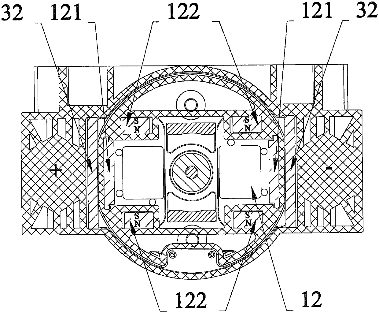
[0055] On the basis of embodiment one, as attached figure 2 As shown, there are 2 pairs of permanent magnets 122, each pair is respectively fixed on both sides of the upper cover 123, and the N poles of one pair of permanent magnets 122 point in the opposite direction, and the N poles on the same side point in the same direction.

Embodiment 3

[0057] On the basis of embodiment two, as attached figure 1 As shown, the actuation system 2 includes a contact spring 25 . The upper end of the contact spring 25 is connected to the bottom of the bridge terminal assembly 23 .


PUM


Abstract

The invention relates to a sealed type direct current contactor with high breaking capacity. The sealed type direct current contactor with high breaking capacity is characterized in that a reaction spring and a bridge terminal assembly are respectively arranged at the lower end and upper end of a push rod; a moving iron core is arranged in an electromagnetic coil and is connected with the push rod; a contact assembly is fixedly arranged above the electromagnetic coil; a casing and an arc extinguishing cover form a sealing cavity; an action system, a contact system and a magnetic circuit system are respectively arranged in the sealing cavity; the arc extinguishing cover comprises a metal ceramic sheet, a permanent magnet and an upper cover; the upper cover is connected and sealed with the casing; the metal ceramic sheet and the permanent magnet are respectively and fixedly arranged at the two ends and two sides of the upper cover. The sealed type direct current contactor has the beneficial effect that the electric arc generated by the disconnecting of a main contact is effectively extended by the metal ceramic sheet in a strong magnetic field which is generated by the permanent magnet, a metal oxide in the metal ceramic sheet can be decomposed by the effect of the electric arc to absorb a large amount of heat, and a large amount of electric arc energy is consumed, so that the electric arc can be quickly extinguished.

Description

technical field [0001] The invention relates to the field of low-voltage electrical switches, in particular to a sealed DC contactor. Background technique [0002] As one of the important components in the automatic control system, the DC contactor is specifically an automatic switcher used to switch on or off the DC main circuit with load or a large-capacity control circuit. The main control object is the motor, and it is also used For other electrical loads, such as electric heaters, electric welding machines, lighting equipment, etc. At the same time, the DC contactor can not only switch on and off the circuit, but also has the function of low voltage release protection. In addition, the contactor has a large control capacity, which can meet the operation requirements of frequent operation and remote control. [0003] The electromagnets of existing DC contactors generally use double-winding coils. Specifically, a pair of auxiliary normally closed contacts is set at the ...

Claims


Application Information

Patent Timeline
IPC IPC(8): H01H50/02H01H50/58
CPCH01H50/023H01H50/58
Inventor 肖延安钟圣舟曹俊敏林国军
Owner SHENZHEN BUSBAR SCI TECH DEV
Why Eureka
Try Eureka