Charging and discharging control device and control method for energy storage super-capacitor of electric workover rig

An electric workover rig, charge and discharge control technology, applied in battery circuit devices, circuit devices, emergency protection circuit devices, etc., can solve problems such as uncontrollable current, slow disconnection speed of DC contactor, and damage to circuit units, etc., to achieve The effect of safe and reliable operation

Inactive Publication Date: 2016-04-20
CHINA UNIV OF PETROLEUM (BEIJING)
View PDF5 Cites 12 Cited by
  • Summary
  • Abstract
  • Description
  • Claims
  • Application Information

AI Technical Summary

Problems solved by technology

However, in practical applications, existing figure 2 The common outstanding problem of the bidirectional DC / DC converter shown is: when using the bidirectional DC / DC converter device, it must be ensured that the DC voltage on the bus side is higher than the DC voltage on the supercapacitor side, otherwise, when the bus side suddenly drops When the power is turned on, the supercapacitor side will immediately discharge to the bus side through the diode D2 of the IGBT switch tube VG2. The arc phenomenon cannot be disconnected, causing the "straight-through" phenomenon between the super capacitor side and the DC bus side of the energy storage device, causing the problem that the super capacitor charges the DC bus with an uncontrollable current, and there is a risk of causing damage to the circuit unit due to overcurrent
If a DC circuit breaker is used instead of DC contactors KM1 and KM2 and KM3 and KM4 for protection, on the one hand, its cost is too high; Tube VG2 has been damaged

Method used


Image

  • Charging and discharging control device and control method for energy storage super-capacitor of electric workover rig
  • Charging and discharging control device and control method for energy storage super-capacitor of electric workover rig
  • Charging and discharging control device and control method for energy storage super-capacitor of electric workover rig

Examples


Embodiment Construction

[0038] The present invention will be described in detail below in conjunction with the accompanying drawings and specific embodiments. The following description is only for demonstration and explanation, and does not limit the present invention in any form.

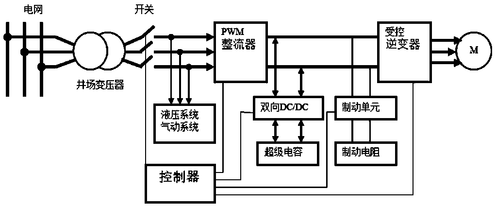
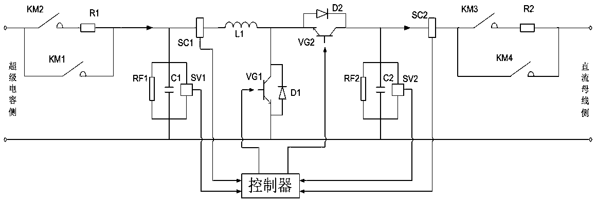
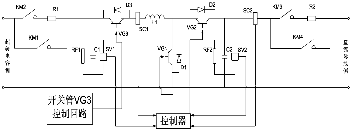
[0039] The electric workover rig energy storage supercapacitor charging and discharging control device has a supercapacitor, a bidirectional DC / DC converter connected with the supercapacitor, and a PWM rectifier connected with the bidirectional DC / DC converter. Here, the bidirectional DC / DC converter of the energy storage supercapacitor charge and discharge control device of the electric workover rig is a non-isolated DC / DC converter, and a bidirectional DC / DC converter is added to the main circuit of the bidirectional DC / DC converter The main circuit control device, the main circuit control device of the bidirectional DC / DC converter is connected with the main circuit of the bidirectional DC / DC converter, and the bidirect...


PUM


Abstract

The invention relates to a charging and discharging control device for an energy storage super-capacitor of an electric workover rig. A bidirectional DC/DC converter of the device is a non-isolation type DC/DC converter; a bidirectional DC/DC converter main circuit control device is arranged on a main circuit of the bidirectional DC/DC converter, and is connected with the main circuit of the bidirectional DC/DC converter; by control over on and off of the bidirectional DC/DC converter main circuit control device, out-of-control overcurrent of the main circuit of the bidirectional DC/DC converter is avoided. In actual application, the main circuit of the bidirectional DC/DC converter and the main circuit control device can meet the power requirement of the electric workover rig in a way of parallel connection of n circuits; according to the charging and discharging control device for the energy storage super-capacitor of the electric workover rig and the control method, uncontrollable factors and risk of damage of charging current of the super-capacitor to the bus side can be avoided, and safe and reliable operation of an electric control system of the electric workover rig can be guaranteed.

Description

technical field [0001] The invention relates to the field of power electronics technology, in particular to an energy storage supercapacitor charging and discharging control device and control method for an electric workover rig. Background technique [0002] Bidirectional DC voltage converter, also known as bidirectional DC / DC converter, is a kind of DC converter that can adjust the bidirectional transmission of energy according to the needs, that is, it converts the DC voltage supplied by the input terminal into a higher, lower or reverse voltage. To the voltage level of the DC voltage circuit. Conversion is performed using periodically operated electronic switches and one or more energy storage elements. In the field of electric energy, these converters are also called DC chopper controllers, and are used in DC uninterruptible power systems, aviation power systems, supercapacitor and battery energy storage systems, electric vehicles, hybrid energy vehicles, fuel cells an...

Claims


Application Information

Patent Timeline
Patent Type & Authority Applications(China)
IPC IPC(8): H02H7/12H02M3/155H02J7/00E21B19/00
CPCE21B19/00H02H7/1213H02J7/00H02M3/155
Inventor 梁志珊谭程吴志昊王景桐郝荣
Owner CHINA UNIV OF PETROLEUM (BEIJING)
Why Eureka
Try Eureka