
Double-excitation synchronous non-inductive rectifying circuit

A technology of rectification circuit and circuit, which is applied in the direction of electrical components, adjustment of electric variables, high-efficiency power electronic conversion, etc., can solve the problems of large output volume, inability to realize synchronous rectification, and low efficiency of low-voltage converters, and achieve the solution of large volume, energy saving The effect of removing the output inductance and simplifying the cumbersome driving and filtering circuits

Inactive Publication Date: 2016-04-20
AEROSPACE CHANGFENG CHAOYANG POWER SUPPLY
View PDF3 Cites 2 Cited by
  • Summary
  • Abstract
  • Description
  • Claims
  • Application Information

AI Technical Summary

Problems solved by technology

[0004] The present invention creates a brand-new secondary synchronous rectification technology in the field of switching power supplies at home and abroad, that is, the secondary side of the double-excited double-transformer is respectively designed as a new synchronous rectification structure with the same name end complementary, aiming to solve the problem of traditional double-excited circuit secondary The bottleneck of synchronous rectification and the disadvantages of large output volume and low efficiency of traditional low-voltage converters

Method used


Image

  • Double-excitation synchronous non-inductive rectifying circuit
  • Double-excitation synchronous non-inductive rectifying circuit
  • Double-excitation synchronous non-inductive rectifying circuit

Examples


Embodiment Construction

[0030] Based on the attachment, the invention is elaborated in detail to make the advantages and characteristics of the invention more easily understood by the technical personnel of the art, so as to make a clearer definition of the protection scope of the present invention.

[0031] The specific implementation of the invention in practical applications:

[0032] The invention provides the application range of rectification technology in the field of dual transformers and dual stress: suitable for high -efficiency rectification of the power supply of DC / DC modules, and the full range of input voltage includes: DC12V, DC24V, DC48V, DC110V, DC300V, DC500V voltage level, output to DC3.3VApplication of DC5.0V, DC12V, DC15V, DC24V.

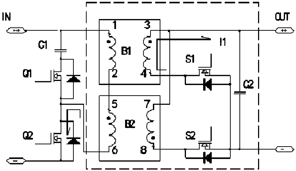
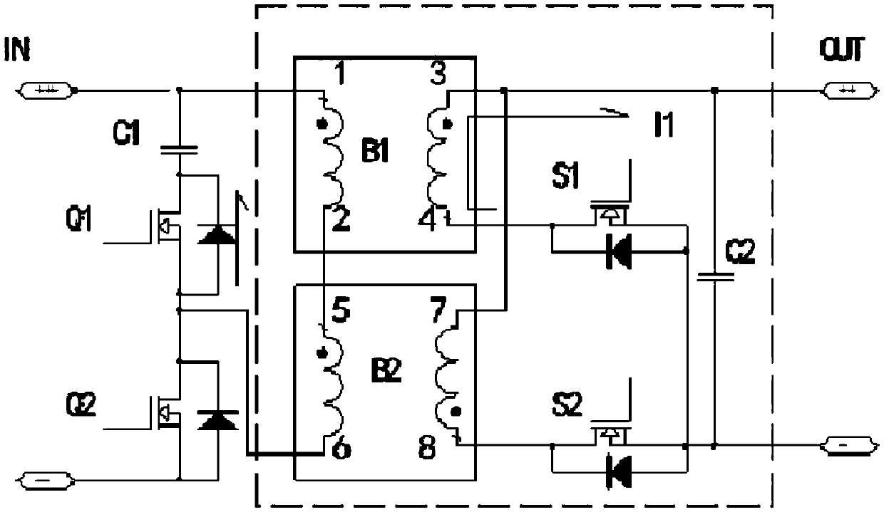
[0033] A dual -excitement synchronization without sensory rectifier circuit, which includes two high -frequency isolation transformers B1 and B2, secondary rectification self -discovery dual MOS tube S1 and S2 and secondary output capacitors, the two high...


PUM


Abstract

The invention relates to a double-excitation synchronous non-inductive rectifying circuit. A brand-new double-excitation synchronous non-inductive rectifying technology is created and disclosed. The circuit comprises double high-frequency isolation transformers, secondary rectifying MOS transistors and secondary output capacitors. A converter primary circuit is a double-excitation circuit, and the double-excitation synchronous non-inductive rectifying technology is adopted for a converter secondary circuit. According to the technology, the synchronous rectifying function of an active clamp circuit secondary rectifying circuit is achieved through the double-excitation combination thought, the double-excitation MOS transistors are conducted in a staggered mode through synchronous triggering, conducting voltage drop of common rectifier diodes is reduced, and a follow current inductor needed for secondary output of a forward circuit is omitted through a flyback voltage transformation secondary inductor. The problem that the voltage drop power consumption of a low-voltage high-power output rectifier tube is large in a double-excitation circuit is solved. The problems that a traditional low-voltage converter is large in output size and low in efficiency are solved. According to the technology, it is achieved that the size of a low-voltage direct current output power source is reduced by 30% and the efficiency of the low-voltage direct current output power source is improved by 8% under the same power and electric parameters.

Description

Technical field [0001] The present invention belongs to the field of secondary rectifier circuits of switching power supply, which involves a dual excitement synchronization without sensory rectifier circuit. Background technique [0002] Synchronous rectification technology is a hotspot in recent years. It is mainly used in the field of low -voltage and large currents. The purpose is to solve the problem of on -demand loss of the continuous flow pipe.The general diode continuity is adopted, and its turnover resistance is large. When it is applied to large current occasions, it consumes a lot.The MOS tube with a very small cross resistance instead of the diode can solve the loss problem, but at the same time put forward higher requirements for the drive circuit. [0003] At present, the secondary rectifier circuit of the switching power supply at home and abroad is commonly used: positive stimulus synchronous rectifier circuit, half -bridge synchronous rectifier circuit, and the ...

Claims


Application Information

Patent Timeline
Patent Type & Authority Applications(China)
IPC IPC(8): H02M3/335
CPCH02M3/33592H02M1/0048Y02B70/10
Inventor 刘建华高海燕
Owner AEROSPACE CHANGFENG CHAOYANG POWER SUPPLY
Features
  • Generate Ideas
  • Intellectual Property
  • Life Sciences
  • Materials
  • Tech Scout
  • Unparalleled Data Quality
  • Higher Quality Content
  • 60% Fewer Hallucinations
Learn More