Supercharge Your Innovation With Domain-Expert AI Agents!

Negative pressure control system and method for electrolysis smoke

A negative pressure control and flue gas technology, applied in the field of electrolytic flue gas negative pressure control system, can solve the problems of reduced heat dissipation of the electrolytic cell, affecting the heat dissipation of the electrolytic cell, and increased molecular ratio, and achieves reduced fugitive emissions, good heat dissipation effect, Effect of Energy Consumption Reduction

Active Publication Date: 2016-04-27
SNTO TECH GRP
View PDF3 Cites 4 Cited by
  • Summary
  • Abstract
  • Description
  • Claims
  • Application Information

AI Technical Summary

Problems solved by technology

[0003] However, changes in temperature will affect the flue gas density and the line loss of the exhaust fan, which will cause fluctuations in the negative pressure of the electrolytic flue gas and affect the heat dissipation of the electrolytic cell.
When the temperature is high, the negative pressure is low, the heat taken away by the flue gas is reduced, and the heat dissipation of the electrolytic cell is reduced, resulting in an increase in the cell temperature, melting of the furnace side, and an increase in the molecular ratio, resulting in poor cell stability and increased energy consumption; Flue gas negative pressure fluctuates due to external factors. If the absolute value of negative pressure is too high, energy will be wasted. If the absolute value of negative pressure is too small, the gas collection efficiency of the electrolyzer will be reduced, and the fugitive emission of fluorine-containing flue gas from the plant will increase, which is not conducive to Environmental friendly
Therefore, the electrolytic flue gas collection system of the related art has the disadvantages of poor heat dissipation effect of the electrolytic cell, insufficient stability of the cell condition, increased energy consumption, and weak environmental protection performance

Method used


Image

  • Negative pressure control system and method for electrolysis smoke

Examples


Embodiment Construction

[0021] In order to facilitate the understanding of the present invention, the present invention will be described more fully below with reference to the associated drawings. Preferred embodiments of the invention are shown in the accompanying drawings. However, the present invention can be embodied in many different forms and is not limited to the embodiments described herein. Rather, these embodiments are provided for the purpose of making the disclosure of the present invention more thorough and comprehensive.

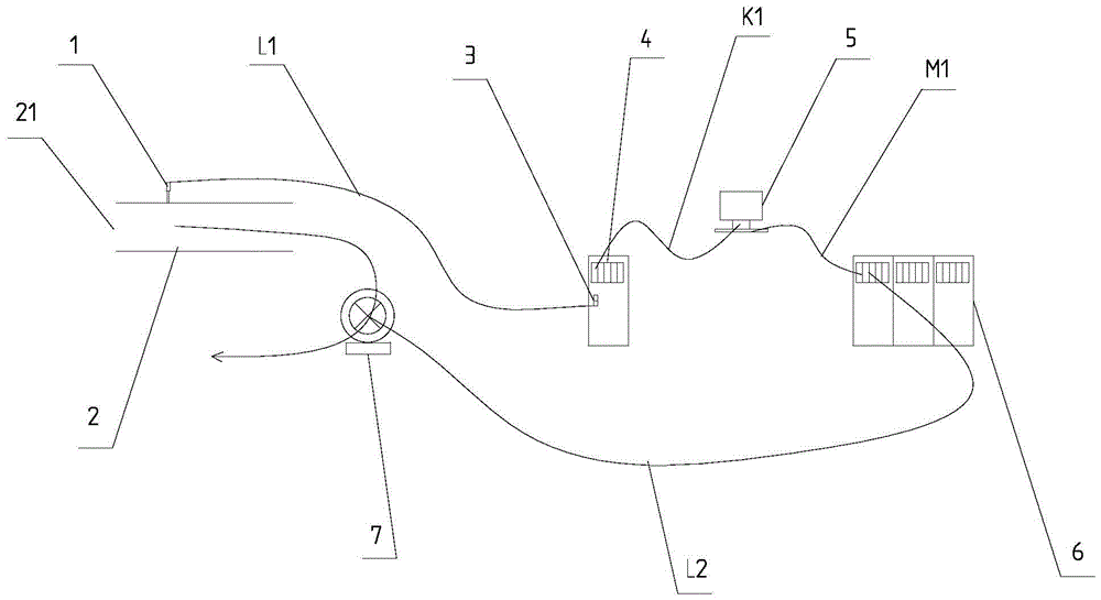
[0022] refer to figure 1 As shown, a negative pressure control system for electrolytic flue gas of the present invention includes a main smoke pipe 2 and several smoke pipes (not shown), the outlets of several smoke pipes are all connected with the entrance 21 of the main smoke pipe 2, so The electrolytic flue gas negative pressure control system also includes a pressure sensor 1, a signal isolator 3, a programmable logic controller 4, a frequency conversion contro...


PUM


Abstract

The invention provides a negative pressure control system for electrolysis smoke. The negative pressure control system comprises a main smoke pipe and a plurality of branch smoke pipes, wherein outlets of the plurality of branch smoke pipes are communicated with an inlet of the main smoke pipe; and the negative pressure control system also comprises a pressure sensor, a signal isolator, a programmable logic controller, a variable frequency control host computer, a frequency converter and a smoke exhaust fan, wherein the pressure sensor is arranged on the main smoke pipe, the pressure sensor, the signal isolator and the programmable logic controller are sequentially connected through an electric signal transmission line, the variable frequency control host computer is connected with the programmable logic controller through an optical signal transmission line, the frequency converter is connected with the variable frequency control host computer through an optical signal transmission line and an electric signal transmission line and is connected with the smoke exhaust fan through an electric signal transmission line. Compared with the prior art, the negative pressure control system has the beneficial effect that an electrolytic tank good in heat radiating effect, stable in tank condition, relatively low in energy consumption and excellent in environmental protection performance.

Description

【Technical field】 [0001] The invention relates to the technical field of aluminum electrolysis flue gas collection, in particular to an electrolysis flue gas negative pressure control system. 【Background technique】 [0002] A large amount of fluorine-containing flue gas is produced during the aluminum electrolysis process. Most aluminum factories use the flue gas dry purification system to recover and process the fluorine-containing flue gas. Flue gas in the flue pipe, the flue gas containing fluorine in the main flue pipe is mixed and reacted with alumina powder, and then the bag filter is used to realize gas-solid separation, and the purified flue gas is finally discharged through the chimney. During the production process, the exhaust fan operates at a fixed power. [0003] However, changes in temperature will affect the density of flue gas and the line loss of the exhaust fan, which will cause fluctuations in the negative pressure of the electrolytic flue gas and affect...

Claims


Application Information

Patent Timeline
Patent Type & Authority Applications(China)
IPC IPC(8): C25C3/22C25C3/20
CPCC25C3/20C25C3/22
Inventor 柳葛贤王博一洪波敬叶灵
Owner SNTO TECH GRP
Features
  • R&D
  • Intellectual Property
  • Life Sciences
  • Materials
  • Tech Scout
  • Unparalleled Data Quality
  • Higher Quality Content
  • 60% Fewer Hallucinations
Learn More