A pulsating two-way impactor

A technology of impactor and impact valve, which is applied in the direction of drilling driving device, drilling equipment, earthwork drilling and production in the wellbore, can solve the problems of no axial impact, achieve the vibration of the drill string, prolong the service life, and the technology Obvious effect

Active Publication Date: 2017-10-10
CHINA PETROCHEMICAL CORP +1
View PDF3 Cites 2 Cited by
  • Summary
  • Abstract
  • Description
  • Claims
  • Application Information

AI Technical Summary

Problems solved by technology

Patent Nos. 200910058083.9, 201310014444.6, and 201020567011.5 have described in detail, and designed special impact drilling tools. It can also be seen from the above that the designed special impact drilling tools can only produce torsional impact and do not have the function of axial impact; Functional drilling tools can not produce torsional impact

Method used


Image

  • A pulsating two-way impactor
  • A pulsating two-way impactor
  • A pulsating two-way impactor

Examples


Embodiment 1

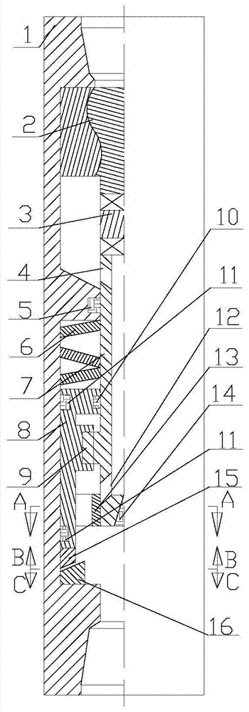
[0022] Such as figure 1 , the power mechanism 2 is installed in the upper part of the housing 1, and is connected with the central shaft 7 through the coupling 3, the upper part of the central shaft 7 is processed with a bypass hole 4, the lower part is processed with a bypass hole 12, and the lower end of the central shaft 7 is installed with a check valve 14. A sealing device 5 is installed between the housing 1 and the central shaft 7, a sealing device 11 is installed between the impact valve 8 and the housing 1, a sealing device 10 is installed between the impact valve 8 and the central shaft 7, and the impact valve 8 and the housing A spring 6 is installed between 1, the central shaft 7 is connected with the impact valve 8 through a spline group 9, the sliding sleeve 13 is installed at the bottom of the impact valve 8, the upper impact block 15 is installed at the lower end of the impact valve 8, and the lower impact block 16 is installed at the shell 1 lower end, the upp...

Embodiment 2

[0024] On the basis of Embodiment 1, the following simplification measures can also be made to the above embodiment.

[0025] One is that the installation of the sealing device 11 can be omitted under the premise of satisfying the workpiece machining accuracy between the housing 1 and the central shaft 7 and between the shock valve 8 and the housing 1 and the central shaft 7 .

[0026] The 2nd, can directly utilize impact valve 8 lower ends and housing 1 lower annular groove inner convex edge to form impact fit and omit upper and lower impact blocks.

[0027] The third is that the sliding sleeve 13 and the shock valve 8 can be of an integral structure, or of a split combined structure.

[0028] Fourth, the inclination angle and direction of the impact contact surfaces of the upper impact block and the lower impact block should be adjusted as needed to achieve the best axial and rotational impact effects.

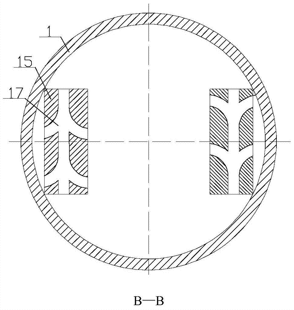
[0029] The drain groove of the upper impact block 15 has dual function...


PUM


Abstract

The invention discloses a pulsating two-way impactor. The pulsating two-way impactor comprises a shell power mechanism and an impact mechanism, wherein the impact mechanism includes a coupling, a central shaft, a spring, a sliding sleeve and an impact valve, and the central shaft There is a radial bypass hole connected with the upper and lower annular grooves built in the housing. The lower part of the central shaft forms an axial sliding fit connection with the impact valve through a spline group. The impact valve and the spring above it are arranged in the lower annular groove of the housing. Inside, the sliding sleeve is arranged on the impact valve, and the lower end of the impact valve forms an impact fit with the inner convex edge of the lower annular groove of the housing. The pulsating two-way impactor can simultaneously produce the dual effects of axial impact and torsional impact. The combination of axial impact and torsional impact can not only induce axial vibration of the drill string, reduce frictional resistance during sliding drilling, reduce the risk of drill sticking due to differential pressure, and increase The pressure on bit can weaken the impact of decompression, and can increase the instantaneous cutting force of the drill bit to prevent stick-slip vibration. It also has the advantages of simple structure, convenient operation, convenient installation, safety and reliability.

Description

technical field [0001] The invention relates to the field of special equipment for oil and gas drilling, coal bed methane drilling, geological exploration and mine drilling, in particular to a pulsating two-way impactor. Background technique [0002] With the increasingly difficult development of oil and gas fields and the rapid development of drilling technology, the number of wells with complex structures such as deep wells, ultra-deep wells, extended-reach wells, horizontal wells with long horizontal sections, and multi-level lateral wells is increasing day by day. It is still one of the key technical bottlenecks restricting the drilling speed increase. Among them, the PDC bit has the characteristics of high drilling speed, low cost and mature manufacturing process, which plays a certain positive role in the drilling speed increase. It is used in the drilling process of various types of wells. However, due to the influence of factors such as wellbore type and formation ro...

Claims


Application Information

Patent Timeline
Patent Type & Authority Patents(China)
IPC IPC(8): E21B4/16
Inventor 李文飞周延军夏文安李玄烨于承朋董怀荣牛洪波耿应春刘晓艳
Owner CHINA PETROCHEMICAL CORP
Why Eureka
Try Eureka