Elevator steel wire rope tension automatic regulation system

An automatic adjustment, wire rope technology, applied in the field of elevators, can solve the problems that cannot be well guaranteed, the tension of each wire rope cannot be guaranteed, and the safety of passengers is affected. The effect of the number of parts

Inactive Publication Date: 2016-05-04
YUNGTAY ELEVATOR EQUIP CHINA
View PDF5 Cites 4 Cited by
  • Summary
  • Abstract
  • Description
  • Claims
  • Application Information

AI Technical Summary

Problems solved by technology

However, in fact, each wire rope is independent, and the tensioning device of each wire rope is also independent. Each wire rope is cut by the installer on site. It is difficult to ensure that the length of the wire rope is consistent. Therefore, the size requirements are passed in the general method. Confirm that the tension of each steel wire rope cannot be guaranteed to be consistent at all. What's worse is that there is no good method for measuring the tension of steel wire ropes at present, and it is difficult to ensure that the tension of each steel wire rope is consistent
Even if the tension of each wire rope can be guaranteed to be almost the same during installation, factors such as wear, rotation angle, and consistency of parameters in each batch may cause new imbalances in actual use, and it is difficult for maintenance personnel to confirm
[0004] For the tension of the steel wire rope which involves major safety issues of elevators, although the regulations require automatic equalization, due to existing technical problems, each manufacturer has no way to guarantee it well. In addition, there is no direct testing tool, and self-inspection and official inspection can only pass. The indirect method is roughly confirmed. Therefore, this problem has plagued the industry for many years and cannot be guaranteed at all. It has become a hidden danger that seriously affects the safety of passengers.

Method used


Image

  • Elevator steel wire rope tension automatic regulation system
  • Elevator steel wire rope tension automatic regulation system
  • Elevator steel wire rope tension automatic regulation system

Examples


Embodiment 1

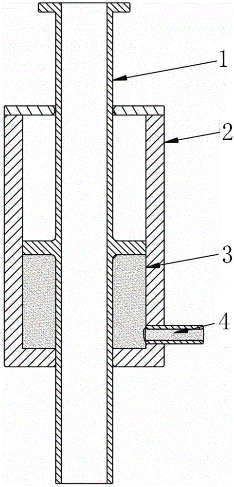
[0029] In this embodiment, the piston 1 includes a piston rod and a piston head, and the piston heads of all the pistons 1 have the same cross-sectional area. The piston head is located in the middle of the piston rod, the piston rod is a hollow structure and its two ends are respectively located outside the cylinder body 2, and the tail end pull rod 7 of the elevator wire rope is packed into the piston rod and fixedly connected with one end of the piston rod.

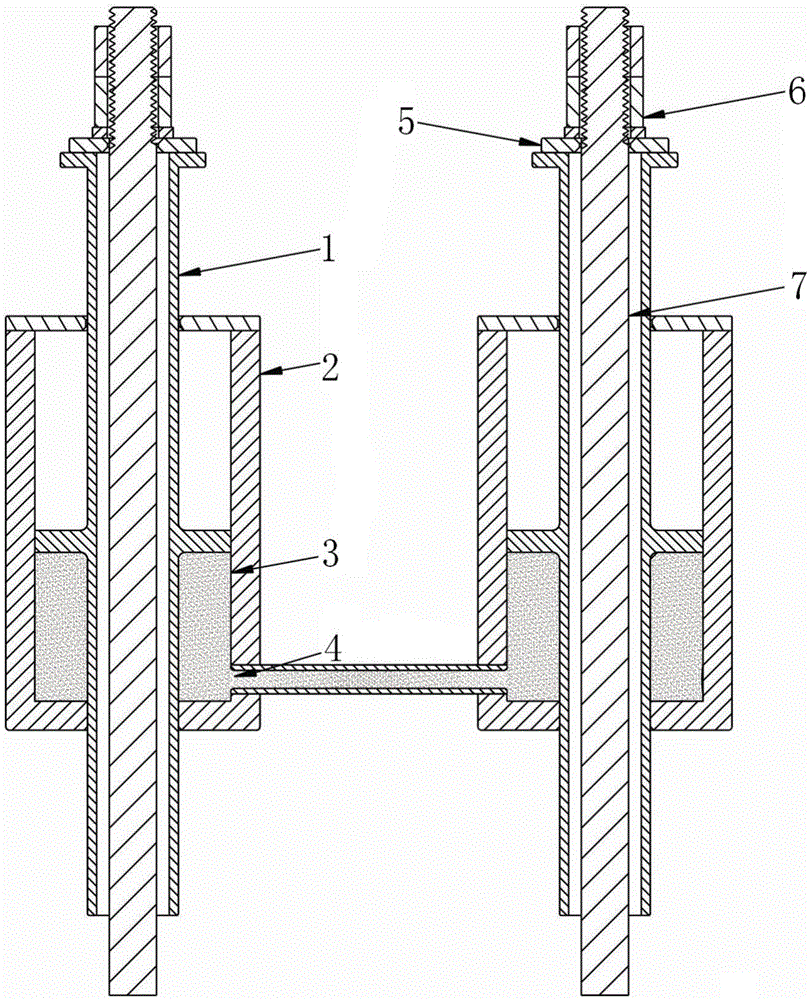
[0030] Such as figure 2 As shown, the tail end pull rod 7 of the elevator steel wire rope passes through the piston 1, and is fixed on the upper end of the piston 1 through the gasket 5 and the nut 6. The piston 1 is installed in the cylinder body 2, and the piston 1 and the cylinder body 2 form an inner cavity 3, and the inner cavity Water is housed in the cavity 3, and the tension force of the wire rope acts directly on the piston 1, and the piston 1 acts on the water in the cavity 3 again.

[0031] After the tail ...

Embodiment 2

[0038] In this embodiment, the piston 1 includes a piston rod and a piston head, and the piston heads of all the pistons 1 have the same cross-sectional area. The piston head is located in the middle of the piston rod, the piston rod is a hollow structure and its two ends are respectively located outside the cylinder body 2, and the tail end pull rod 7 of the elevator wire rope is packed into the piston rod and fixedly connected with one end of the piston rod.

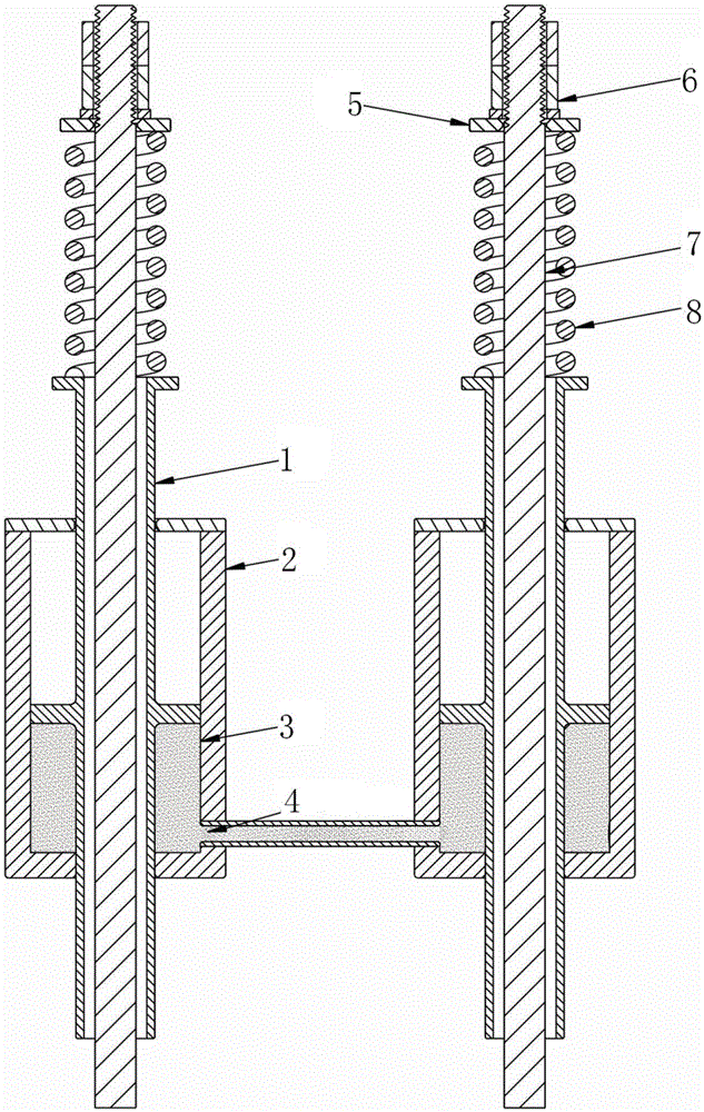
[0039] Such as image 3 As shown, the rope head spring assembly of the traditional wire rope is installed on the upper end of the piston 1, specifically, the tail end pull rod 7 of the elevator wire rope passes through the piston rod of the hollow structure of the piston 1, then passes through the damping spring 8, and passes through The washer 5 and the nut 6 are fixed on the upper end of the piston 1 , the lower end of the damping spring 8 is against the upper section of the piston rod, and the upper end of the dampi...


PUM


Abstract

The invention discloses an elevator steel wire rope tension automatic regulation system which comprises a plurality of cylinder bodies. A piston is mounted in each cylinder body; each piston is fixed to a tail end pull rod of one elevator steel wire rope and can freely move in the corresponding cylinder body; an inner cavity is formed by each piston and the corresponding cylinder body; and all the inner cavities are communicated mutually and are filled with liquid for transferring a pressure to form a closed communicated liquid system. Tensions of the steel wire ropes are acted on the pistons by the tail end pull rods and generate a certain pressure on liquid in the inner cavities by the pistons, the inner cavities of all the cylinder bodies are communicated, and thus, according to a principle that the liquid can transfer the pressure towards each direction in a size unchanged manner, liquid pressures in different inner cavities connected together finally reach a dynamic balance to enable acting forces of the liquid on different pistons to be equal, so that automatic regulation on the tensions of all the steel wire ropes is achieved. According to the invention, uniformity of the tension of each steel wire rope is achieved, wear to the steel wire ropes greatly stressed and grooves matched with the steel wire ropes greatly stressed is reduced, and the elevator steel wire rope tension automatic regulation system is beneficial for prolonging the service life of an elevator traction system.

Description

technical field [0001] The invention relates to elevators, and in particular belongs to an elevator wire rope tension automatic adjustment system. Background technique [0002] The elevator car is generally connected to the counterweight by multiple steel wire ropes, and the steel wire ropes connecting the car and the counterweight are suspended in the groove of the traction wheel. The elevator relies on the friction between the wire rope and the groove to provide traction. The traction force is the basis to ensure the safe operation of the elevator, and the traction force generated by the friction between the wire rope and the groove is largely affected by the tension of the wire rope. When the traction force does not meet the design requirements, the car will slip in a slight case, and the control system will shut down due to a fault. In severe cases, the traction force will not be enough to slide freely. The general load change occurs when the car door is opened and pass...

Claims


Application Information

Patent Timeline
Patent Type & Authority Applications(China)
IPC IPC(8): B66B7/10
CPCB66B7/10
Inventor 涂长祖赵建兵许志华
Owner YUNGTAY ELEVATOR EQUIP CHINA
Why Eureka
Try Eureka