Biogas liquid and biogas residue solid-liquid separation method

A technology of solid-liquid separation and biogas residue, which is applied in separation methods, filtration separation, chemical instruments and methods, etc., can solve the problems of large vibration amplitude, easy blockage of filter screen, high residue content of biogas slurry, etc., and achieve strong adaptability of raw materials, The effect of good raw material adaptability and compact overall structure

Inactive Publication Date: 2016-05-04
NANJING AGRI MECHANIZATION INST MIN OF AGRI +1
View PDF6 Cites 9 Cited by
  • Summary
  • Abstract
  • Description
  • Claims
  • Application Information

AI Technical Summary

Problems solved by technology

[0003] The existing biogas slurry and biogas residue separation equipment is mainly composed of fixed filter screen, screw shaft, cylinder, frame, power and other parts. The principle of the equipment with this structure is that the biogas residue is separated by the screw shaft. The biogas slurry is rotated and pushed out, and the biogas slurry is precipitated by extrusion. After separation, the biogas slurry has a high slag content and the sewage is turbid. It is far away from the discharge and living utilization standards, and the value of the biogas slurry cannot be fully utilized. jam
[0004] Considering the material characteristics of biogas slurry and biogas residue (moisture content is about 95%), that is, the water in

Method used


Image

  • Biogas liquid and biogas residue solid-liquid separation method
  • Biogas liquid and biogas residue solid-liquid separation method
  • Biogas liquid and biogas residue solid-liquid separation method

Examples


Embodiment

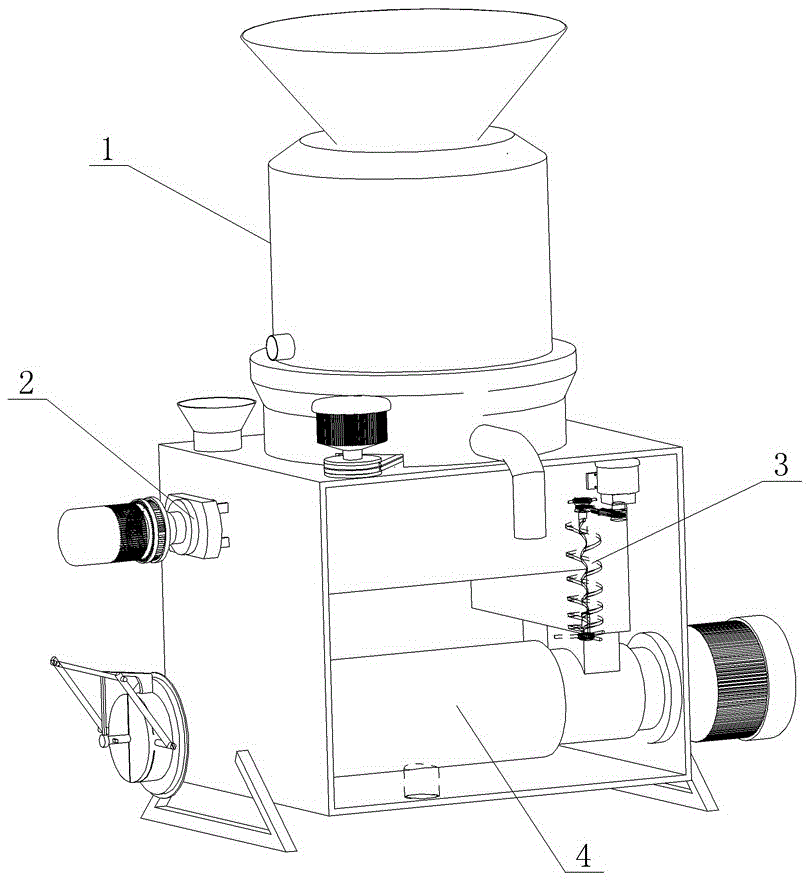
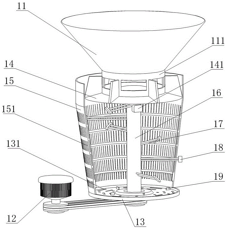
[0032] The method for solid-liquid separation of biogas slurry and residue in this embodiment adopts a centrifugal mechanism 1, an auxiliary stirring mechanism 2, a shaftless screw pressing mechanism 3, and a squeezing mechanism 4 that are connected to each other sequentially through pipe connections from front to back to separate the biogas slurry and residue. , the centrifugal mechanism 1 is provided with a feed hopper 11, and the auxiliary stirring mechanism 2 is provided with a secondary feed hopper, comprising the following steps:

[0033] 1) Put the biogas slurry and residue into the centrifugal mechanism 1 from the primary feeding hopper 11 to perform the first-stage centrifugal dehydration, discharge the separated biogas slurry, and transport the separated biogas residue to the auxiliary stirring mechanism 2;

[0034] 2) Add rice husk or straw powder to the auxiliary mixing mechanism 2 through the secondary feeding hopper, and separate the biogas residue in the auxiliar...


PUM


Abstract

The invention relates to a biogas liquid and biogas residue solid-liquid separation method, and belongs to the technical field of general physical separating operation. The method adopts a centrifugal mechanism, an auxiliary stirring mechanism, a non-shaft spiral pressing mechanism and a squeezing mechanism for separation of a biogas liquid and a biogas residue, and the centrifugal mechanism, the auxiliary stirring mechanism, the non-shaft spiral pressing mechanism and the squeezing mechanism communicate with one another through pipe connectors orderly from front to back. The method comprises the following steps: 1) the biogas liquid and the biogas residue are subjected to first-stage centrifugal dehydration with the centrifugal mechanism, at the moment, 15-20% of water is removed, the separated biogas liquid is discharged, and the separated biogas residue is transported to the auxiliary stirring mechanism; 2) with addition of rice hull or straw powder, the rice hull or straw powder is stirred and mixed with the biogas residue in the auxiliary stirring mechanism, then the mixed material is discharged from the interior of the auxiliary stirring mechanism; and 3) the material after being mixed evenly is transported to the squeezing mechanism from the auxiliary stirring mechanism through the non-shaft spiral pressing mechanism and is subjected to second-stage squeezing dehydration with the squeezing mechanism, and at the moment, 10-15% of water is removed. The method has the advantages that the separation efficiency of the biogas liquid and the biogas residue is high, the raw materials have good adaptability and the water content of a filter cake is low.

Description

technical field [0001] The invention relates to a method for solid-liquid separation of biogas slurry and biogas residue, which belongs to the technical field of general physical separation operations. Background technique [0002] At present, the function of biogas slurry and biogas residue separation equipment is mainly to separate the biogas slurry that has been preliminarily treated, so that the residual biogas residue can be highly filtered, and the sewage can reach the standard of self-use and further treatment and discharge or make biogas slurry fertilizer . [0003] The existing biogas slurry and biogas residue separation equipment is mainly composed of fixed filter screen, screw shaft, cylinder, frame, power and other parts. The principle of the equipment with this structure is that the biogas residue is separated by the screw shaft. The biogas slurry is rotated and pushed out, and the biogas slurry is precipitated by extrusion. After separation, the biogas slurry ...

Claims


Application Information

Patent Timeline
IPC IPC(8): C02F11/12B01D33/11
CPCC02F11/127B01D33/11C02F11/122C02F2201/002
Inventor 朱德文赵维松谢虎曹杰王鹏军李瑞容曲浩丽陈永生马标韩柏和陈明江
Owner NANJING AGRI MECHANIZATION INST MIN OF AGRI
Why Eureka
Try Eureka