
Resource gradient cracking system

A cracking system and resource-based technology, which is used in the gasification of granular/powdered fuels, special forms of dry distillation, and the preparation of liquid hydrocarbon mixtures. problem, to achieve the effect of continuous cracking process and great promotion and application value

Inactive Publication Date: 2016-05-04
刘振亮
View PDF8 Cites 10 Cited by
  • Summary
  • Abstract
  • Description
  • Claims
  • Application Information

AI Technical Summary

Problems solved by technology

[0002] During the treatment of garbage and waste products, a large amount of solid waste such as waste plastics and waste tires will be obtained. The treatment of these wastes has become a major technical problem, and the usual method is cracking to generate cracking gas and cracking Crude oil, to realize the recycling of resources; most of the cracking equipment in the prior art cannot be continuously produced, and need to start the furnace, cool, slag, feed, close the furnace, heat and crack, and then repeat the above steps after completion, the cracking process Cooling is required every time, a lot of energy is wasted, a lot of toxic gas and dust are emitted, and the cracking efficiency is extremely low
There are also continuous cracking equipment, the disadvantage of which is that the material is not stirred evenly, the cracking is easily wrapped by charcoal ash, the cracking is not complete, and the cracking efficiency is also not high.

Method used


Image

  • Resource gradient cracking system
  • Resource gradient cracking system
  • Resource gradient cracking system

Examples


Embodiment Construction

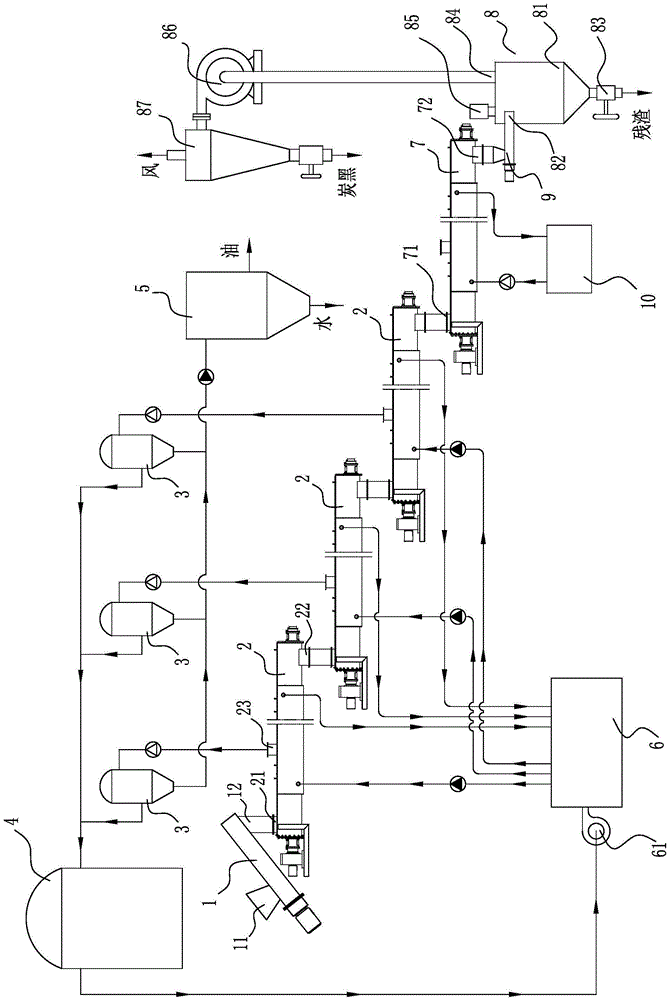
[0029] Exemplary embodiments according to the present invention are described in detail below with reference to the accompanying drawings. Here, it should be noted that, in the drawings, the same reference numerals are assigned to substantially the same components in structure and function, and redundant descriptions about the substantially same components are omitted to make the description more concise.

[0030] like figure 1 As shown, the recycling cascade cracking system includes:

[0031] see Figure 7 , the sealing feeding device is used to add the material that needs to be cracked without gas overflow, including the feeding device feeding hopper 11 and the feeding device discharging port 12;

[0032] This embodiment adopts the double helix continuous cracking furnace 2 connected in three stages in series, wherein the first stage mainly plays the role of drying and preliminary cracking, the second stage mainly plays the role of cracking, and the third stage mainly play...


PUM


Abstract

The invention discloses a resource gradient cracking system. The resource gradient cracking system comprises a sealed feeding device, at least two stages of double helix continuous cracking furnaces, a material cooling device and a carbon black air-separation device which are sequentially arranged; the double helix continuous cracking furnaces generate cracked gas which is then further separated into combustible noncondensable gas and petroleum, wherein the combustible noncondensable gas is supplied to a gas heat conducting oil boiler for supplying heat energy to the double helix continuous cracking furnaces; the carbon black air-separation device is used for extracting and separating carbon black from tailings. According to the resource gradient cracking system disclosed by the invention, materials are continuously stirred, torn and pushed while heated in the double helix continuous cracking furnace, such that physical and chemical forms of the materials change continuously, and the cracking process of the materials is continuous, stable and thorough; combustible gas, petroleum and carbon black can be obtained from waste plastic or waste rubber, and the cracking energy is from the system per se; the materials are continuously cracked while moving forwards in the sealed system, such that the cracking is relatively thorough without emission of pollutants, and the cracking efficiency is relatively high.

Description

technical field [0001] The invention relates to a cracking system, in particular to a cracking system that utilizes its own energy for cracking and obtains various resources. Background technique [0002] In the process of garbage and waste treatment, a large amount of solid wastes such as waste plastics, waste tires, etc. will be obtained. The treatment of these wastes has become a major technical problem, and the commonly used method is to crack to generate cracked gas and cracking. Crude oil, realizes the recycling of resources; most of the cracking equipment in the prior art cannot be continuously produced. It needs cooling every time, wastes a lot of energy, emits a lot of toxic gas and toxic dust, and the cracking efficiency is extremely low. There are also continuous cracking equipment, the disadvantage is that the material is not uniformly stirred, the cracking is easily covered by carbon ash, the cracking is not complete, and the cracking efficiency is also not hig...

Claims


Application Information

Patent Timeline
Patent Type & Authority Applications(China)
IPC IPC(8): C10J3/48C10G1/10C10G1/00C10B53/07C10B49/02C10B57/02
CPCY02P20/143C10J3/48C10B49/02C10B53/07C10B57/02C10G1/00C10G1/10C10G2300/1003
Inventor 刘国田代吉发张大鹏李振衡
Owner 刘振亮
Learn More