A wet cuttings method test system and test method for coal mine dynamic disasters

A technology for dynamic disasters and testing systems, applied in earth-moving drilling, wellbore/well components, flushing wellbore, etc., can solve the problems such as the inability to continue drilling cuttings method, drilling water, and wet pulverized coal, etc., to achieve the working principle Simple and reliable, easy to collect and weigh, to measure the effect of precise results

Inactive Publication Date: 2019-05-03
CHINA UNIV OF MINING & TECH
View PDF7 Cites 0 Cited by
  • Summary
  • Abstract
  • Description
  • Claims
  • Application Information

AI Technical Summary

Problems solved by technology

[0003] When the drilling cuttings method is implemented, the method is greatly affected by the underground geological conditions of the coal mine. In the prior art, the drilling cuttings method adopts the dry cuttings method, that is, when the drilling machine is used to drill the coal seam, it needs to be discharged through the drill hole. The amount of dry coal powder is used to identify the risk of dynamic disasters in coal mines according to the conventional identification method. Once a certain degree of water is mixed into the coal powder, the detection of the risk of dynamic disasters in coal mines cannot be achieved by the cuttings method.
However, in reality, the natural moisture content of coal seams in many mines is relatively high. When using drilling rigs to drill holes, the coal dust often appears wet, and even water may flow out of the borehole, resulting in the failure to discharge the coal powder normally. Therefore, the drilling cuttings method cannot proceed
But in fact, there may still be high-stress areas inside the coal body, which will cause safety hazards in coal mines and is not conducive to the safe production of coal mines.

Method used


Image

  • A wet cuttings method test system and test method for coal mine dynamic disasters
  • A wet cuttings method test system and test method for coal mine dynamic disasters
  • A wet cuttings method test system and test method for coal mine dynamic disasters

Examples


Embodiment 1

[0035] A wet drill cuttings testing system for coal mine dynamic disasters, including a drilling device for drilling pulverized coal, a collecting device for collecting pulverized coal, and solid-liquid separation for drying the pulverized coal drilled by the drilling device unit.

[0036] The drilling device in the wet drilling cuttings method test system for coal mine dynamic disaster is a water-passing drilling rig system, such as figure 1 As shown, the water-passing drilling rig system includes a drilling rig 1, a water-passing drill pipe 3 connected to the output end of the drilling rig 1, and a water-passing drill bit 5 installed at the end of the water-passing drill pipe 3. The water-passing drill pipe 3 and the drilling rig 1 are reliably connected by a connecting piece 2. A water inlet 4 is provided on one side of the connecting piece 2, and the water inlet 4 is connected with the water inlet channel arranged axially inside the water-passing drill pipe 3, and the water i...

Embodiment 2

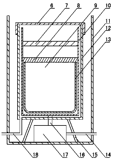
[0058] The difference between this embodiment and the first embodiment is that the rotating inner shell 10 is omitted from the rotating separation assembly and replaced by a rotating bracket. Such as Figure 4~5 As shown, the rotating support includes a bottom plate 20 and a plurality of arc-shaped vertical plates 19 vertically fixed on the upper surface of the bottom plate 20. The arc-shaped vertical plates 19 are uniformly fixed on the upper surface of the bottom plate 20. The top of the rotating shaft of the pneumatic device 17 is detachably connected to the bottom of the bottom plate 20, and the rotating bracket can be driven to rotate when the pneumatic device 17 rotates.

[0059] The upper opening of the filter cloth pocket 13 is placed on the bottom plate 20, the periphery of the pocket body is fixedly connected with the arc-shaped vertical plate 19, and the upper opening of the filter cloth pocket 13 is provided with a secondary filter screen 8 and a primary filter screen...

Embodiment 3

[0063] In this embodiment, the difference from embodiment 1 is that the rotating shafts of the rotating inner shell 10 and the pneumatic device 17 adopt a non-detachable design, and the rotation axis of the pneumatic device 17 passes through the water collecting shell 12 and then Rotating the bottom connection of the inner shell 10 drives it to rotate. Such as Image 6 As shown, the rotating inner shell 10 is provided with a net cover 21, the upper part of the net cover 21 is open, the net cover 21 and the rotating inner shell 10 are connected and fixed by a detachable fixing member 22, and the pneumatic device 17 is driving the rotating inner shell 10. When rotating, the mesh cover 21 is driven to rotate at the same time, and the fixing member 22 can be realized in a variety of detachable ways, such as a plug-in type.

[0064] A filter cloth pocket 13 is placed inside the net cover 21, the upper end of the filter cloth pocket 13 is open, and the pocket body is attached to the in...


PUM


Abstract

The invention relates to a wet-type drilling cuttings method test system and test method for coal mine dynamic disasters, and belongs to the field of coal mine dynamic disaster monitoring equipment. The test system is characterized by comprising a drilling device which is used for conducting wet-type drilling on a coal bed and a solid-liquid separation device which conducts solid-liquid separation on a water-coal mixture obtained from drilling through the drilling device, wherein the solid-liquid separation device comprises a power unit and a rotating separation mechanism driven by the power unit. The test method comprises the following steps that 1, a monitoring area is selected; 2, wet-type drilling is conducted; mixture of coal dust and water is collected; 4, solid-liquid separation is conducted; 5, weighing is conducted, and the weight of coal dust is recorded; 6, data analysis is conducted. In the wet-type drilling cuttings method test system for the coal mine dynamic disasters, even if the natural moisture content of the coal bed is high, the dangerous level of the dynamic disasters of the coal bed can be identified through a drilling cuttings method, therefore, potential safety hazards are eliminated, and safety production of a coal mine is facilitated.

Description

Technical field [0001] A wet drill cuttings method testing system and testing method for coal mine dynamic disasters belongs to the field of coal mine dynamic disaster monitoring equipment. Background technique [0002] Due to its simple equipment, intuitive detection results, and easy on-site operation and discrimination, the drill cuttings method has become a more common monitoring method used at home and abroad for monitoring coal mine dynamic disasters. The basic principle of the drill cuttings method is to use a drilling rig to drill holes with a diameter of Φ42-50mm in the coal seam. According to the amount of discharged coal powder and its changing law and related dynamic effects, the identification of the risk of coal mine dynamic disasters is realized. For coal under certain conditions, under normal stress, the stress state of coal at different drilling depths is different, and the amount of pulverized coal drilled at this time is also different. When the stress concent...

Claims


Application Information

Patent Timeline
Patent Type & Authority Patents(China)
IPC IPC(8): E21B49/00E21B21/06
CPCE21B21/065E21B49/005
Inventor 曹安业刘志刚窦林名王常彬魏兵程贺贺
Owner CHINA UNIV OF MINING & TECH
Why Eureka
Try Eureka