MIMO through-wall radar based single-side double-point squint imaging method of building

A technology of through-wall radar and imaging method, which is applied in the direction of radio wave reflection/re-radiation, utilization of re-radiation, measurement devices, etc., and can solve problems such as performance degradation, low realizability, and harsh detection environment

Inactive Publication Date: 2016-05-04
CHENGDU UNIVERSITY OF TECHNOLOGY +1
View PDF2 Cites 21 Cited by
  • Summary
  • Abstract
  • Description
  • Claims
  • Application Information

AI Technical Summary

Problems solved by technology

[0003] For wall layout imaging, the influence of weak internal stationary target echoes can be ignored. Due to the characteristics of wall specular reflection, the existing methods to obtain all wall echoes of buildings require at least through-wall radar on both sides of adjacent buildings. , from two perspectives perpendicular to the surface of the walls on both sides, the "front-facing" synthetic aperture multi-point detection is carried out respectively, that is, the bilateral multi-point front-facing detection of the building, the echo data collection and processing are very complicated, and the surrounding of the building is required to meet the bilateral multi-point Facing the detection conditions squarely, the achievability is not high
[0004] For internal stationary target imaging, only single-view synthetic aperture detection or Multiple Input Multiple Output (MIMO) real aperture detection on one side of the building can obtain sufficient target echoes, but the wall echoes are characterized by strong noise. Wave interference, the side lobes of the wall image will cover up the static t

Method used


Image

  • MIMO through-wall radar based single-side double-point squint imaging method of building
  • MIMO through-wall radar based single-side double-point squint imaging method of building
  • MIMO through-wall radar based single-side double-point squint imaging method of building

Examples


Embodiment 1

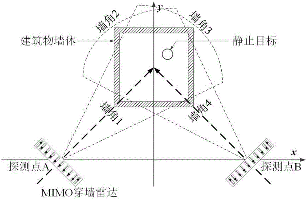
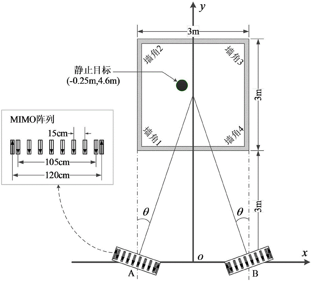
[0048] Embodiment 1: see Figure 1 to Figure 9 , set in the electromagnetic simulation software CST such as image 3 In the simulation scenario shown, the MIMO through-the-wall radar is a radar with two transmissions and eight receptions, that is, the MIMO array is composed of two transmitting antennas and eight receiving antennas, a total of sixteen transmitting and receiving channels, and two transmitting antennas At both ends of the array, eight receiving antennas are evenly distributed in the middle of the array. The distance between adjacent transmitting and receiving antennas is 7.5cm, and the distance between adjacent receiving antennas is 15cm; the wall thickness of a square building is 10cm, and the relative dielectric constant is 6. The length of the single side wall is 3m, simulate a small ball at the position inside (-0.25m, 4.6m) as the static target; on the parallel line 3m away from the single side wall of the building, respectively select two detection position...


PUM


Abstract

The invention discloses an MIMO through-wall radar based single-side double-point squint imaging method of a building. An MIMO through-wall radar carries out real-aperture squint detection at two detection points selected in the single side of the building, and collected real aperture echoes of the two points from two squint images which include part corners of the building and static objects in the building via a backward projection imaging algorithm. Overlapped fusion and 2D constant false alarm detection are carried out on the two squint images, the integrity of all corner images of the building is ensured, the layout of all walls can be determined, corner image sidelobe and multipath phantom interference are inhibited, distribution of static objects therein can be determined, and a panorama image of the building including clear corner images and static object images is obtained finally. The corner image and the static object image can be used to determine the wall layer out and the static object distribution respectively, and imaging detection for the wall layout and the internal static objects of the building is realized.

Description

technical field [0001] The invention relates to a radar imaging method, in particular to a unilateral two-point squint imaging method for buildings based on MIMO through-wall radar. Background technique [0002] In the application of building imaging detection based on through-the-wall radar, the wall layout of the building and the internal stationary targets (furniture, home appliances, stationary human body, etc.) are the other two basic detection objects besides the moving human body. The attenuation of wall penetration causes the echo intensity of the wall to be much higher than that of the internal static target, so different processing methods are required to obtain the wall layout image and the static target image. [0003] For wall layout imaging, the influence of weak internal stationary target echoes can be ignored. Due to the characteristics of wall specular reflection, the existing methods to obtain all wall echoes of buildings require at least through-wall radar...

Claims


Application Information

Patent Timeline
IPC IPC(8): G01S13/90G01S13/88G01S7/292G01S7/28
CPCG01S7/2813G01S7/2927G01S13/888G01S13/90G01S13/9041
Inventor 贾勇钟晓玲郭勇刘剑刚崔成华陈俊杰吉江涛
Owner CHENGDU UNIVERSITY OF TECHNOLOGY
Why Eureka
Try Eureka