
Profile machining center

A processing center and profile technology, applied in the direction of metal processing equipment, metal processing machinery parts, manufacturing tools, etc., can solve the problems of limiting the processing range of workpieces, not solving rigid problems, and long processing time, so as to reduce labor intensity and production costs , Improve the efficiency of profile processing and improve the overall rigidity

Inactive Publication Date: 2016-05-11
JIANGMEN INTIN NUMERICAL CONTROL MACHINE TOOL CO LTD
View PDF12 Cites 3 Cited by
  • Summary
  • Abstract
  • Description
  • Claims
  • Application Information

AI Technical Summary

Problems solved by technology

Such a processing form requires multiple clamping of workpieces on different machine tools, which has high labor intensity for workers, takes a long time for processing, and has high production costs and low processing efficiency.
On the other hand, most of the existing profile processing centers imitate the design of similar imported products, using welded steel structure bed, which is limited by the quality of domestic steel and welding stress relief technology, the stability of the bed is poor, and it can only be used in low precision requirements. Door and window processing and other industries
Although some profile processing equipment adopts cast iron bed, the overall structure is still not separated from the influence of welding bed, the problem of rigidity is not solved, and it can only be used in light cutting occasions
In addition, the integral manufacture of the bed structure and the workbench also limits the processing range of the workpiece

Method used


Image

  • Profile machining center
  • Profile machining center

Examples


Embodiment Construction

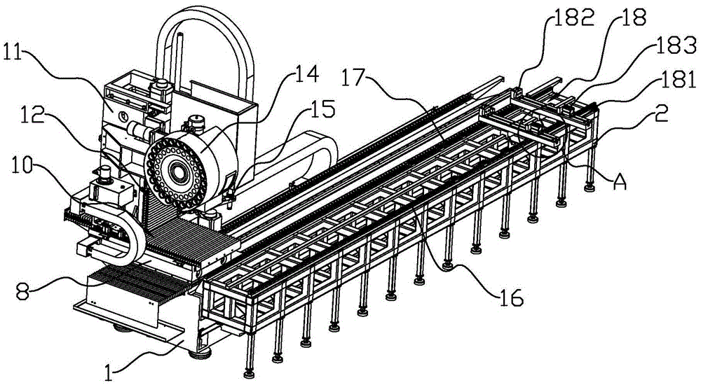
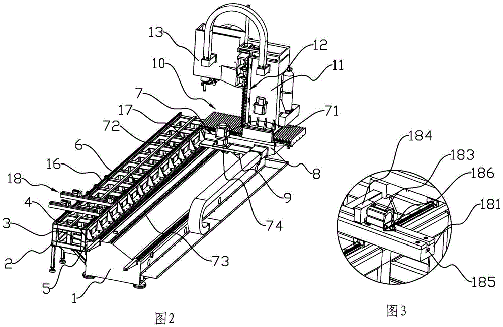
[0013] refer to figure 1 , figure 2 , a profile processing center of the present invention, comprising a base 1, the base 1 is formed by integral casting of metal, its transverse section is trapezoidal, a steel frame workbench 2 is connected to the front of the base 1, and the steel frame workbench 2 The side is provided with a right-angled connector 3, and the base 1 is respectively provided with first and second datum planes 4, 5 corresponding to the two right-angled sides of the right-angled connector 3, and several screws 6 pass through the right-angled connector. The two right-angled sides of the piece 3 are respectively connected and fixed with the first and second reference planes 4 and 5, and the base 1 is provided with a Y-axis support platform 8 driven by an X-axis transmission mechanism 7 and can move longitudinally. The Y-axis support platform The lower part of the 8 is provided with a saddle 9 that cooperates with the rear inclined surface of the trapezoid to in...


PUM


Abstract

The invention discloses a profile machining center which comprises a base. The front portion of the base is connected with a steel frame worktable. A right-angle-shaped connecting piece is arranged on the side face of the steel frame worktable. The base is provided with a first datum plane and a second datum plane which are correspondingly matched with the two right-angle edges of the right-angle-shaped connecting piece. A plurality of screws penetrate the two right-angle edges of the right-angle-shaped connecting piece to be connected and fixed to the first datum plane and the second datum plane. An X-axis transmission mechanism, a Y-axis transmission mechanism and a Z-axis transmission mechanism are used for driving and linking; a machining tool is automatically replaced through a tool changing mechanical arm; multiple types of machining of a profile can be completed on the same equipment; multiple times of workpiece clamping is not needed; the labor intensity of workers and production cost are reduced; and the profile machining efficiency can be improved. In addition, the base is of a trapezoidal structure integrally formed through metal in a casting manner, a saddle matched with the base is designed, and overall rigidity of the equipment is greatly improved; the profile machining center of a movable pillar structure has high machining precision; and the profile machining center can be used for machining parts such as robot mechanical arms with the requirement for high precision.

Description

technical field [0001] The invention relates to a metal processing equipment, in particular to a profile processing equipment. Background technique [0002] With the continuous development of production technology, there are more and more profile machining center machine tools used for drilling, milling, face milling and tapping of aluminum-copper profiles and steel profiles. In the prior art, when processing workpieces with long grooves or multiple grooves and other processing positions, the groove positions are usually first planed and milled with a planer, and then other processing positions are cut, milled and drilled with a processing machine tool. Such a processing form requires multiple clamping of the workpiece on different machine tools, the labor intensity of the workers is high, the processing takes a long time, and the production cost is high and the processing efficiency is low. On the other hand, most of the existing profile processing centers imitate the desi...

Claims


Application Information

Patent Timeline
IPC IPC(8): B23P23/02B23Q1/01B23Q3/155B23Q5/34
CPCB23P23/02B23Q1/01B23Q3/155B23Q5/34
Inventor 唐兵仿李志坚张力达李永裕陈丽源
Owner JIANGMEN INTIN NUMERICAL CONTROL MACHINE TOOL CO LTD
Learn More