Assembly method of vacuum drainage system for mine shaft

A vacuum drainage and assembly method technology, applied in drainage, safety devices, mining equipment, etc., can solve problems such as insufficient water storage capacity, limited suction of water pumps, complex structure installation, etc., and achieve long-term safe and reliable operation. Maintenance workload Small, low-cost production effects

Inactive Publication Date: 2013-10-02
刘意豪
View PDF8 Cites 2 Cited by
  • Summary
  • Abstract
  • Description
  • Claims
  • Application Information

AI Technical Summary

Problems solved by technology

[0003] At present, in the underground mining process, a large amount of groundwater often gushes out. Generally, the large amount of groundwater flows into the underground water tank in a natural flow through the drainage ditch, and then collects the water through the drainage device of the tank. Drain to the ground, due to the short suction of the water pump used in the drainage device, the water tank will not be designed too deep, the suction of the water pump is limited, and the water cannot be drained. Water must be pumped at any time during "peak, valley, and flat", which will increase electricity consumption and increase mining costs. Once water leakage occurs in the underground mining area, due to insufficient water storage capacity, there will be no more The time for workers to escape is extremely prone to casualties
[0004] The patent document with the application number of 87200749.9 discloses a compressed air mine drainage device, which has a small displacement, complicated structure installation, and slow drainage speed. Once a water leakage accident occurs, it is difficult to drain water in time.

Method used


Image

  • Assembly method of vacuum drainage system for mine shaft
  • Assembly method of vacuum drainage system for mine shaft

Examples


Embodiment 1

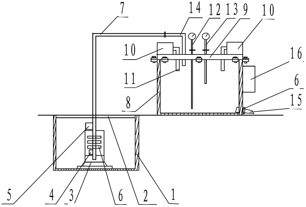
[0022] A support 3 is set at the bottom of the cement pool 1 in the mine, a vacuum pumping pipe 7 is set on the support 3, and a grate 2 is set above the cement pool 1; a vacuum box 8 is set on the ground, and a top plate 9 is set above the vacuum box 8, and the top plate 9 corresponds to the vacuum box 8 Setting, set multiple sets of fixing seats at the junction of the top plate 9 and the vacuum box 8, and fix them with bolts; vacuum pumps 10 are arranged on both sides above the top plate 9, and the suction port 11 of the vacuum pump 10 is set in the vacuum box 8 through the reserved hole of the top plate 9; A controller 16 is arranged on one side of the vacuum box 8 .

Embodiment 2

[0024] An inductor 4 is arranged above the water outlet of the vacuum suction pipe 7, a water level alarm 5 is arranged above the sensor 4 of the vacuum suction pipe 7, and at least three control valves 6 are arranged between the sensor 4 and the water level alarm 5; Set a liquid level indicator 12 and a vacuum gauge 13, set a water inlet elbow 14 on the top plate 9, connect the water inlet elbow 14 to the vacuum suction pipe 7, set a drain pipe 15 at the bottom of the vacuum box 8, and set a control valve on the drain pipe 15 6.

Embodiment 3

[0026] Vacuum suction pipe 7, vacuum box 8, top plate 9, water inlet elbow 14, drain pipe 15 are made of low carbon steel.


PUM


Abstract

Provided is an assembly method of a vacuum drainage system for a mine shaft. The vacuum drainage system is composed of a cement pit, a perforated strainer, a support, an inductor, a water level alarm, control valves, a vacuum water pumping pipe, a vacuum box, a top board, vacuum pumps, air suction ports, a liquid level indicator, a vacuometer, a water inlet bent pipe, a drainage pipe and a controller. The support is installed at the bottom of the cement pit in the mine shaft, the vacuum water pumping pipe is installed on the support, and the perforated strainer is installed above the cement pit; the vacuum box is installed on the ground, the top board is installed above the vacuum box, and the top board and the vacuum box are installed oppositely; the vacuum pumps are installed on two sides of the upper side of the top board, and the controller is installed on one side of the vacuum box. The assembly method resolves the technical problem that the suction stroke of a water pump in an existing drainage device is insufficient, can achieve complete drainage of accumulated water in an underground water bin of a deep mine, reduces consumption of electric energy, improves the utilization rate of the water pump, reduces maintenance costs of the water pump, guarantees safety in production, and effectively resolves the problems that the suction stroke of the water pump is limited and water leakage accidents and water inrush accidents occur.

Description

technical field [0001] The invention relates to the technical field of mine drainage, in particular to a method for assembling a vacuum drainage system for mines. [0002] Background technique [0003] At present, in the underground mining process, a large amount of groundwater often gushes out. Generally, the large amount of groundwater flows into the underground water tank in a natural flow through the drainage ditch, and then collects the water through the drainage device of the tank. Drain to the ground, due to the short suction of the water pump used in the drainage device, the water tank will not be designed too deep, the suction of the water pump is limited, and the water cannot be drained. Water must be pumped at any time during "peak, valley, and flat", which will increase electricity consumption and increase mining costs. Once water leakage occurs in the underground mining area, due to insufficient water storage capacity, there will be no more The time for worker...

Claims


Application Information

Patent Timeline
Patent Type & Authority Applications(China)
IPC IPC(8): E21F16/00
Inventor 刘意豪
Owner 刘意豪
Why Eureka
Try Eureka