Compressor pump structure and compressor

A compressor and pump body technology, applied in the field of compressors, can solve problems such as high friction power consumption of friction pairs, difficulty in processing cylinders, and reduced performance of compressors, so as to improve work performance, reduce mechanical power consumption, and reduce friction work consumption effect

Active Publication Date: 2016-05-11
ZHUHAI GREE REFRIGERATION TECH CENT OF ENERGY SAVING & ENVIRONMENTAL PROTECTION
View PDF8 Cites 15 Cited by
  • Summary
  • Abstract
  • Description
  • Claims
  • Application Information

AI Technical Summary

Problems solved by technology

[0004] 1. There is a circumferential leakage channel between the above-mentioned piston sleeve and the cylinder, which is the main leakage channel of the compressor, resulting in a decrease in the performance of the compressor
[0005] 2. The above-mentioned piston sleeve needs to be radially limited during assembly, and the short-axis cantilever support of the rotating shaft needs to be used, resulting in a large span of the piston supporting part of the rotating shaft. Under the action of unit force, the deformation and contact stress are too large
[0006] 3. The suction and exhaust passages are distributed on the cylinder wall, which makes the cylinder difficult to process and the processing cost is high
[0007] 4. The outer circular surface of the above-mentioned piston is two sections of arc surface, and two parallel surfaces are distributed in the middle. The piston hole on the matching piston sleeve is also composed of two arc surfaces and two parallel surfaces, resulting in The structure is complex, the processing cost is high, and the processing quality is difficult to guarantee
[0008] 5. The circumferential friction pair between the cylinder and the piston sleeve is a sliding friction pair. The linear velocity of the friction pair and the area of ​​the friction pair are too large during operation, resulting in excessive friction power consumption of the friction pair and affecting the performance of the compressor.

Method used


Image

  • Compressor pump structure and compressor
  • Compressor pump structure and compressor
  • Compressor pump structure and compressor

Examples


Embodiment 1

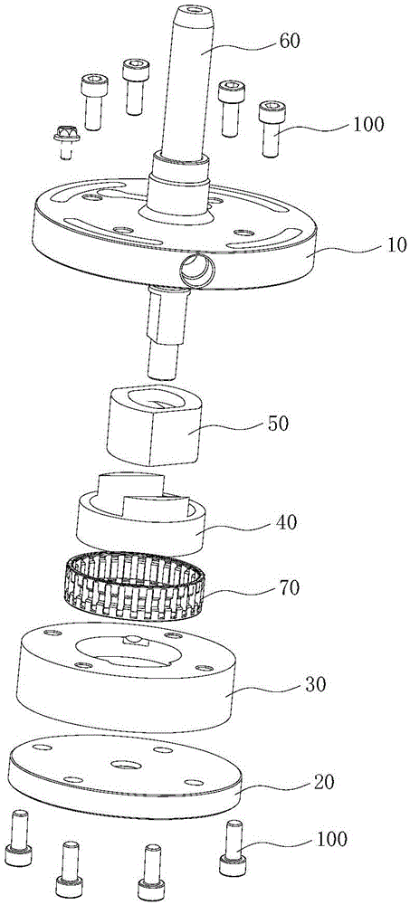
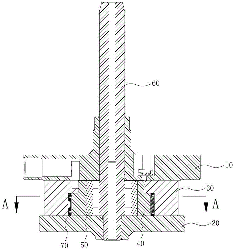
[0047] This embodiment provides a compressor pump body structure, such as figure 1 as well as figure 2 As shown, it includes an upper flange 10, a lower flange 20, a cylinder liner 30, a cylinder 40, a piston 50, a rotating shaft 60 and a needle cage assembly 70, wherein:

[0048] The cylinder liner 30 is located between the upper flange 10 and the lower flange 20, and is fixed by screws 100. The cylinder 40 is arranged in the cylinder liner 30 so as to be rotatable around its own axis, and the piston 50 is located in the cylinder 40, and is relatively The cylinder 40 can slide, but does not rotate relatively;

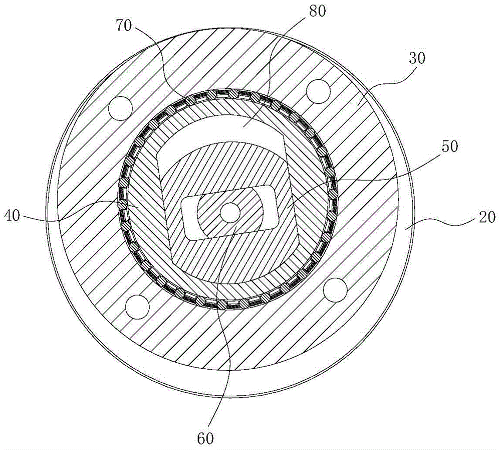
[0049] refer to image 3 , a variable volume cavity 80 is formed between the cylinder liner 30, the cylinder 40 and the piston 50, and the volume of the variable volume cavity 80 can change with the sliding of the piston 50;

[0050]The rotating shaft 60 is set through the upper flange 10, the piston 50 and the lower flange 20 in turn. The axis of the rotating shaf...

Embodiment 2

[0087] This embodiment provides a compressor, including the pump body structure of the compressor in the preferred embodiment 1, specifically, as Figure 22 As shown, the compressor includes a liquid separator assembly 90, a casing assembly 91, a motor assembly 92, a compressor pump body structure 93, an upper cover assembly 94 and a lower cover assembly 95, wherein the liquid separator assembly 90 is arranged on the casing The outside of the assembly 91 is connected to the first air intake passage 101 of the upper flange 10 of the compressor pump body structure 93, the upper cover assembly 94 is assembled on the upper end of the housing assembly 91, and the lower cover assembly 95 is assembled on the upper end of the housing assembly 91. At the lower end, the motor assembly 92 and the compressor pump body structure 93 are located inside the housing assembly 91, and the motor assembly 92 is arranged above the compressor pump body structure 93, and the motor output end of the mo...


PUM


Abstract

The invention discloses a compressor pump structure, and belongs to the field of compressors. A cylinder sleeve is arranged between an upper flange and a lower flange; a cylinder is arranged in the cylinder sleeve; a piston is slidingly arranged in the cylinder; a variable volume cavity is formed among the cylinder sleeve, the cylinder and the piston; a rotating shaft is inserted in the piston; the axis of the rotating shaft is eccentric from the axis of the cylinder, and the eccentric distance is fixed; the rotating shaft drives the piston and the cylinder to rotate; and the piston slides in the cylinder when rotating to change the volume of the variable volume cavity. The cylinder sleeve is arranged, the variable volume cavity is formed among the cylinder sleeve, the cylinder and the piston, and the structure of a piston sleeve is replaced, so that the problem of peripheral leakage channel is not generated anymore, the compressor leakage is radically reduced, and the compressor performance is improved; and the pump structure is simple in machining process and convenient for assembly.

Description

technical field [0001] The invention relates to the field of compressors, in particular to a compressor pump body structure and a compressor. Background technique [0002] At present, the pump body structure of the rotary cylinder compressor usually installs the piston sleeve and the cylinder coaxially, and then places the piston in the piston hole of the piston sleeve. The piston adopts a non-circular structure to prevent the piston from rotating; the suction and discharge The gas passages are all distributed on the cylinder wall. [0003] During the operation of the above-mentioned rotary cylinder compressor, there are the following problems: [0004] 1. There is a circumferential leakage passage between the piston sleeve and the cylinder, which is the main leakage passage of the compressor, resulting in a decrease in the performance of the compressor. [0005] 2. The above-mentioned piston sleeve needs to be radially limited during assembly, and the short-axis cantileve...

Claims


Application Information

Patent Timeline
Patent Type & Authority Applications(China)
IPC IPC(8): F04C18/344F04C29/00F04C29/12
CPCF04C18/344F04C29/00F04C29/12F04C2240/10F04C2240/20F01C21/0809F04C15/0065F04C15/06F04C18/3445F04C23/008F04C29/023F04C2240/60F04C18/0215F04C18/34F25B49/02
Inventor 胡余生杜忠诚徐嘉任丽萍杨森孔令超赵庆富许甲岿丁宁
Owner ZHUHAI GREE REFRIGERATION TECH CENT OF ENERGY SAVING & ENVIRONMENTAL PROTECTION
Why Eureka
Try Eureka