Measuring device of quantum efficiency of CCD device

A quantum efficiency and measurement device technology, applied in the field of testing, can solve the problems of weak light output energy, weakened light energy, and large attenuation of the integrating sphere of the monochromator, so as to improve the utilization rate of light energy, improve the measurement accuracy, and reduce the difficulty of debugging. Effect

Inactive Publication Date: 2016-05-11
THE 41ST INST OF CHINA ELECTRONICS TECH GRP
View PDF4 Cites 16 Cited by
  • Summary
  • Abstract
  • Description
  • Claims
  • Application Information

AI Technical Summary

Problems solved by technology

[0007] First, the volume is too large, it is not easy to move and operate, which will bring some inconvenience to the test;
[0008] Second, the light energy emitted by the monochromator itself is weak, and the attenuation will be large when passing through the integrating sphere with a large aperture, and the CCD under test is far away from the integrating sphere, and the light energy is further weakened. Insufficient noise ratio occurs;
[0009] Third, the standard detector and the CCD under test need to be detected in the same position in turn during the test, but according to the current actual test situation, sometimes not only the CCD bare chip needs to be tested, but also the installed and adjusted CCD camera For the test, due to the obstruction of the shell structure of the CCD camera, it is not easy to determine the specific position of the CCD photosensitive surface, especially in the direction perpendicular to the light-emitting surface of the integrating sphere, there will be a certain deviation in the placement position of the standard detector and the CCD photosensitive surface. Measurement results bring certain errors

Method used


Image

  • Measuring device of quantum efficiency of CCD device
  • Measuring device of quantum efficiency of CCD device

Examples


Embodiment Construction

[0032] The following will clearly and completely describe the technical solutions in the embodiments of the present invention with reference to the accompanying drawings in the embodiments of the present invention. Obviously, the described embodiments are only some, not all, embodiments of the present invention. Based on the embodiments of the present invention, all other embodiments obtained by persons of ordinary skill in the art without creative efforts fall within the protection scope of the present invention.

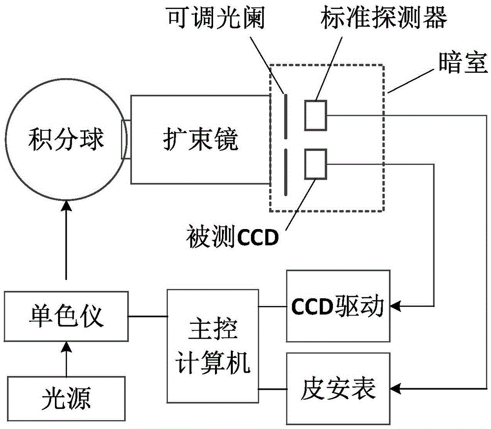
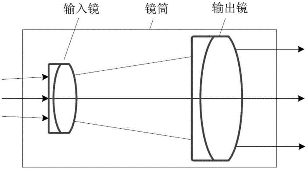
[0033] For the measurement of the quantum efficiency of CCD devices, the key is to obtain a uniform monochromatic light source. Currently, the monochromator + integrating sphere solution is generally used, but at the same time, there are disadvantages such as large system size, serious light energy attenuation, and difficult system debugging. In order to overcome the deficiencies of the prior art, the present invention proposes an improved CCD device quantum efficie...


PUM


Abstract

The invention brings forward a measuring device of the quantum efficiency of a CCD device. The measuring device comprises a light source, a monochromator, an integrating sphere, a beam expander, adjustable diaphragms, a darkroom, a standard detector, a CCD driving circuit, a picoammeter, and a master control computer; the CCD device and the standard detector are arranged in the darkroom; an output port of the monochromator is focused and amplified, collected to an optical fiber bundle, and injected to the integrating sphere; a light outlet of the integrating sphere is additionally provided with the beam expander, light is collected via the beam expander, and the light after collection and collimation enters the darkroom and is projected to the detected CCD or the standard detector via the adjustable diaphragm; and data acquisition is performed via the CCD driving circuit and the picoammeter, and data is transmitted to the master control computer for processing. According to the measuring device, the light outlet of the integrating sphere is additionally provided with the beam expander system so that the uniformity of the light source is improved, the effect of collecting and collimating the light is achieved, and the utilization rate of light energy is increased.

Description

technical field [0001] The invention relates to the technical field of testing, in particular to a measuring device for the quantum efficiency of a CCD device. Background technique [0002] CCD devices are one of the most widely used image sensors in the field of optical imaging, and quantum efficiency is an important basic parameter of CCD devices. Accurate calibration mainly has two meanings: on the one hand, it helps to improve the material selection and design and production process in the device development and production process; on the other hand, it helps the better application of CCD devices. [0003] To realize the precise measurement of the quantum efficiency of CCD devices, the key lies in the acquisition of the monochromatic uniform light source of the area array. It is necessary to ensure that the light energy is evenly and vertically irradiated on the photosensitive surface of the detector, and it is also necessary to ensure that the light source has sufficie...

Claims


Application Information

Patent Timeline
Patent Type & Authority Applications(China)
IPC IPC(8): G01M11/02
CPCG01M11/02G01M11/0207
Inventor 王洪超刘红元应承平王恒飞霍明明姜斌
Owner THE 41ST INST OF CHINA ELECTRONICS TECH GRP
Why Eureka
Try Eureka