Thermal control system of a stationary micro fuel cell cogeneration device

A micro-fuel cell and cogeneration technology, applied in the direction of fuel cell heat exchange, fuel cell additives, etc., can solve the problems of time-consuming, fuel cell stack output power limited in the start-up time, etc., to save volume, shorten Heating time, cost reduction effect

Active Publication Date: 2017-11-07
JINCHENG ABOUND ENERGY CO LTD
View PDF4 Cites 0 Cited by
  • Summary
  • Abstract
  • Description
  • Claims
  • Application Information

AI Technical Summary

Problems solved by technology

When the fuel cell stack is in cold start, it needs to heat the stack through the heat generated by its own work. This process takes a lot of time, so the output power of the fuel cell stack is limited during the start-up time

Method used


Image

  • Thermal control system of a stationary micro fuel cell cogeneration device

Examples


Embodiment 1

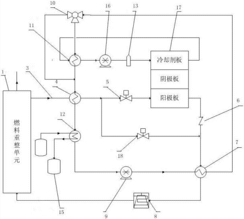
[0024] Such as figure 1As shown, a thermal control system for a residential micro-fuel cell cogeneration device, including a fuel reforming unit 1 for catalytically converting hydrocarbon fuel into hydrogen and a hydrothermal cycle unit connected to the fuel reforming unit 1 , it is characterized in that, the described hydrothermal cycle unit includes airflow pipeline, cooling water circulation loop and cooling liquid circulation loop, and the airflow pipeline includes airflow inlet pipeline 3, No. 1 heat exchanger 4, No. 1 solenoid valve 5, single Direction valve 6, No. 2 heat exchanger 7, condenser 8 and No. 2 solenoid valve 18, the air flow pipeline is divided into two, one is the gas path entering the fuel cell stack, and the other is a bypass, the fuel entering the The gas path of the battery stack is a normal working gas path, and the high-temperature hydrogen-rich mixed gas flow generated by the fuel reforming unit 1 enters the No. The outlet of No. 4 heat exchanger 4 ...


PUM


Abstract

The invention relates to a thermal control system of a stationary micro-fuel cell heat and power cogeneration device. The gas path entering the fuel cell stack in the present invention is a normal working gas path, and the high-temperature hydrogen-rich mixed gas flow generated by the fuel reforming unit enters the No. 1 heat exchanger through the pipeline, and then passes through the No. 1 heat exchanger outlet and passes through the No. 1 solenoid valve Entering the anode plate for power generation, the high-temperature exhaust gas discharged from the anode plate enters the No. 2 heat exchanger through the check valve, then enters the condenser for water vapor separation, and then returns to the reforming unit for recycling; the cooling water pump exchanges heat with No. 4 The cold water is exchanged with the high temperature tail gas discharged from the anode plate through the No. The circulation loop is connected with the cooling water circulation loop through the No. 3 heat exchanger. The cooling cycle unit of the present invention has simple structure and simplified design, saves a lot of parts, greatly saves the volume of the heat and power cogeneration device, and reduces the cost at the same time.

Description

technical field [0001] The invention belongs to the technical fields of fuel cell cogeneration system and energy control, and in particular relates to a thermal control system of a fixed miniature fuel cell cogeneration device. Background technique [0002] The fuel cell cogeneration device uses hydrocarbon fuel (natural gas, biogas, etc.) to convert the hydrogen-rich reformed mixed gas through the fuel reforming unit, and supplies the reformed mixed gas and air to the anode and cathode of the fuel cell stack respectively. , and then generate direct current through electrochemical reaction, and recover the heat in the reforming reaction process and the heat generated in the power production process. [0003] In a fuel cell cogeneration unit, the hydrogen-rich mixed gas stream obtained from the reformer unit is usually at a temperature of 150°C or higher, and must be cooled to between the liquefaction point and 80°C before entering the anode of the fuel cell, or it must be co...

Claims


Application Information

Patent Timeline
Patent Type & Authority Patents(China)
IPC IPC(8): H01M8/04007
CPCH01M8/04007Y02E60/50
Inventor 明其敏郭新新碗海鹰
Owner JINCHENG ABOUND ENERGY CO LTD
Why Eureka
Try Eureka