Planar transformer

A planar transformer, part of the technology, applied in the field of transformers, can solve the problem of inability to adjust leakage inductance and AC resistance, and achieve the effect of changing coupling performance and AC loss, good coupling and good heat dissipation

Active Publication Date: 2016-05-18
杭州博洲电器有限公司
View PDF4 Cites 8 Cited by
  • Summary
  • Abstract
  • Description
  • Claims
  • Application Information

AI Technical Summary

Problems solved by technology

[0004] Aiming at the above defects or improvement needs of the prior art, the present invention provides a planar transformer, which aims to solve the technical problem that the leakage inductance and AC resistance cannot be adjusted according to actual needs in the prior art

Method used


Image

  • Planar transformer
  • Planar transformer
  • Planar transformer

Examples


Embodiment 1

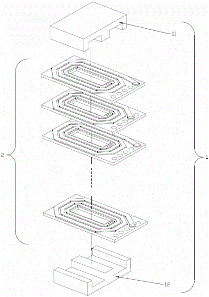
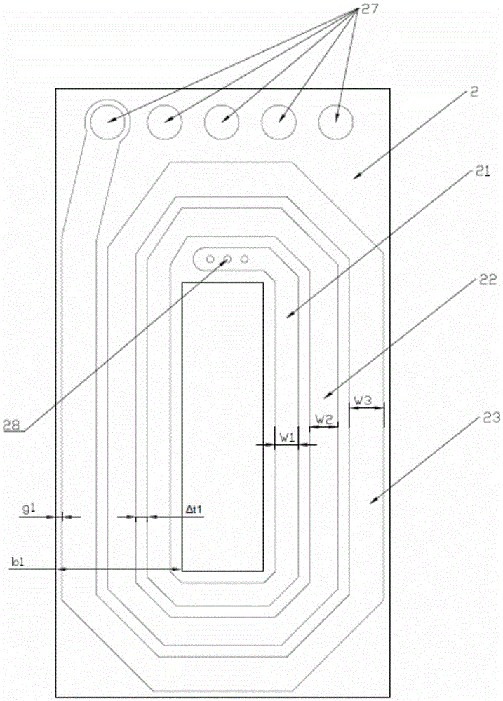
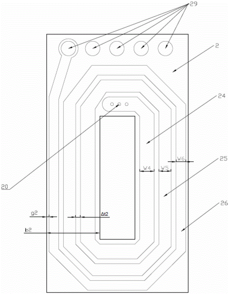
[0020] Such as figure 1 As shown, the planar transformer of this embodiment includes an upper magnetic core, a lower magnetic core, and a multilayer printed circuit board 2 arranged between the upper and lower magnetic cores for providing windings for the planar transformer. The magnetic core 1 provided by this embodiment It includes an upper magnetic core 11 and a lower magnetic core 12 respectively above and below the multilayer printed circuit board 2 . The upper magnetic core 11 and the lower magnetic core 12 are a pair of EE type planar magnetic cores, and may also be other magnetic cores, such as EI magnetic cores, ER magnetic cores and the like. This embodiment takes one coil per layer and three turns of each coil as an example, such as figure 2 As shown, the printed wires 21, 22, 23 on each layer of the multilayer printed circuit board 2 provide a coil around the central part of the magnetic core 1. The coil is printed with copper foil wires, and the printed wires ar...

Embodiment 2

[0042] Such as Figure 4 As shown, in this example, the multilayer printed circuit board in Example 1 is replaced by a plurality of copper sheets, and the coil on each copper sheet is still printed as in Example 1, and the other copper conductors except the coil part are made of stamped or otherwise removed. When copper sheets are used to replace multilayer printed circuit boards, it is equivalent to retaining the copper foil lines on the multilayer printed circuit boards, removing the substrate, and improving the flow capacity. The plurality of copper sheets are connected through through holes 31 . An insulating material needs to be provided between adjacent copper sheets for insulation.

[0043] On the basis of Embodiment 1, copper sheet 3 can be used to replace part or all of the multilayer printed circuit board 2, and at the same time, there is a preset winding ratio between the primary winding and the secondary winding, and the copper sheet 3 and the printed circuit boa...


PUM


Abstract

The invention discloses a planar transformer. The planar transformer comprises an upper magnetic core, a lower magnetic core and multiple flat coils arranged between the upper magnetic core and the lower magnetic core. The adjacent flat coils are insulated. Each flat coil is formed by multiple turns of metal conductors coiled into a spiral shape. The flat coils are vertically projected in space and overlapped vertically. Some flat coils form primary windings of the planar transformer, and the other flat coils form secondary windings of the planar transformer. The planar transformer is characterized in that according to the direction from the center to the outer side of each flat coil, the widths of the turns of each flat coil change as the following form: W1:W2:...:Wn=1:a:...:a(n-1), W represents the widths of the coils, n represents the number of turns of the coils and is larger than or equal to 1, a is larger than or equal to 0.5 and smaller than 1 or a is larger than 1 and smaller than or equal to 1.5, and the widths of the turns of each flat coil change consistently. Magnetic field distribution of the transformer can be changed by changing the widths of the turns of each coil, so that coupling performance and the alternating current loss are changed. The planer transformer has the advantage that leakage inductance and alternating current resistance of the planer transformer can be adjusted according to the actual needs.

Description

technical field [0001] The present invention relates to the field of transformers, more specifically, to a planar transformer. Background technique [0002] In recent years, power electronic equipment has been developing towards smaller volume, higher power density and higher efficiency. As one of the key components in power electronic equipment, transformers also tend to be miniaturized. Traditional wire-wound transformers have long been The request cannot be met. The traditional transformer process is complex and has the problem of large leakage inductance, high cost, and it is difficult to meet the current market demand. [0003] Conventionally, all coils printed on a PCB as transformer windings are of the same width. Contents of the invention [0004] Aiming at the above defects or improvement needs of the prior art, the present invention provides a planar transformer, which aims to solve the technical problem in the prior art that the leakage inductance and AC resis...

Claims


Application Information

Patent Timeline
Patent Type & Authority Applications(China)
IPC IPC(8): H01F27/28
CPCH01F27/2804H01F27/2871H01F2027/2819H01F2027/2857
Inventor 高俊饶波聂中赵映张正卿
Owner 杭州博洲电器有限公司
Why Eureka
Try Eureka