chemical mechanical polisher

A chemical machinery and polishing machine technology, applied in the field of polishing machines, can solve the problems of gaps in the rotating structure, poor positioning accuracy of the polishing head, and large space occupied by the manipulator, so as to improve the installation stability, work reliability, and process improvement. The effect of stability

Active Publication Date: 2018-05-22
HWATSING TECH +1
View PDF8 Cites 0 Cited by
  • Summary
  • Abstract
  • Description
  • Claims
  • Application Information

AI Technical Summary

Problems solved by technology

The application of a rotatable polishing head support to transport wafers has the following problems: 1. There is a gap in the rotating structure of the polishing head support, resulting in insufficient stability of the polishing head support, resulting in poor process stability; 2. Multiple polishing head supports When the polishing heads are polishing at the same time, there will be mutual interference among the polishing heads, which will lead to complicated debugging of the polishing process; 3. The polishing head is suspended on the cantilever of the polishing head bracket, and the protruding cantilever will amplify the rotation error, resulting in the polishing head being loaded and unloaded. Poor positioning accuracy on the platform
The application of manipulators to transport wafers has the following problems: 1. The manipulator takes up a lot of space, resulting in an increase in the overall size of the chemical mechanical polishing machine; 2. The manipulator performs wafer transport, which needs to frequently pick and place wafers, move with the wafers, and the action is complicated. low efficiency

Method used


Image

  • chemical mechanical polisher
  • chemical mechanical polisher
  • chemical mechanical polisher

Examples


Embodiment Construction

[0027] The embodiments of the present invention are described in detail below, and examples of the embodiments are shown in the accompanying drawings. The embodiments described below with reference to the accompanying drawings are exemplary, and are intended to explain the present invention, but should not be construed as limiting the present invention.

[0028] The chemical mechanical polishing machine 100 according to an embodiment of the present invention will be described in detail below with reference to the accompanying drawings.

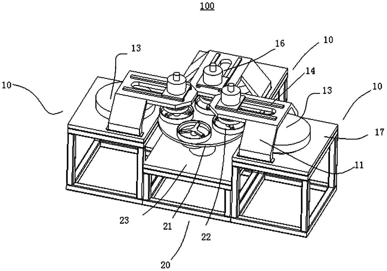
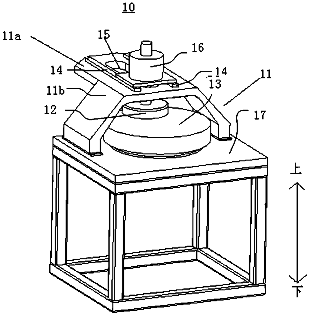
[0029] The chemical mechanical polishing machine 100 according to the embodiment of the present invention may include a plurality of polishing components 10 and a transmission component 20. A plurality of polishing components 10 can be arranged around the transmission component 20, such as figure 1 As shown, a plurality of polishing components 10 are arranged at intervals, and each polishing component 10 may include: a support 11, a polishing head ...


PUM


Abstract

The invention discloses a chemical mechanical polishing machine. The chemical mechanical polishing machine comprises: a plurality of polishing components arranged at intervals and each of the polishing components comprises: a support, a polishing head and a polishing disc, and the polishing The head is arranged on the support and is adapted to move between a polishing position and a transmission position. When the polishing head is in the polishing position, the polishing head is located above the polishing disc; a transmission assembly, the transmission assembly includes : a turntable and a plurality of loading and unloading platforms, a plurality of loading and unloading platforms are arranged on the turntable at intervals and rotate with the turntable, when the polishing head is in the transmission position, the polishing head and the plurality of loading and unloading platforms corresponding to one of the platforms. Therefore, the mounting stability of the bracket is good, the working reliability of the polishing component is high, and the process stability of the polishing machine is good.

Description

Technical field [0001] The invention relates to the technical field of polishing machines, in particular to a chemical mechanical polishing machine. Background technique [0002] In the large-scale integrated circuit production process, it is necessary to use chemical mechanical polishing processes to remove the surface material of the wafer to improve the surface quality. The chemical mechanical polishing machine is the main equipment to complete this work. Generally, chemical mechanical polishing of wafers needs to be performed in multiple processes through multiple polishing modules. [0003] At present, there are mainly two methods for transferring wafers between polishing modules. A wafer transfer method is that the polishing head driving device and the polishing head are arranged on a rotating polishing head support. After the wafer is polished on a polishing disk, the polishing head holder rotates, and the polishing head is transferred to the next polishing disk to polish...

Claims


Application Information

Patent Timeline
Patent Type & Authority Patents(China)
IPC IPC(8): B24B37/04B24B37/27B24B37/34
CPCB24B37/04B24B37/27B24B37/34B24B27/0023B24B27/0069B24B37/105B24B37/30B24B37/345B23Q41/02
Inventor 许振杰王剑陈祥玉王同庆李昆路新春
Owner HWATSING TECH
Why Eureka
Try Eureka