
Strong-core cement-soil tubular pile, construction method and tubular rotary drilling tool

A construction method and cement-soil technology, applied in sheet pile walls, foundation structure engineering, construction, etc., can solve the problems of waste of building materials, segregation, exposed tendons, broken piles, limited bearing capacity and pull-out resistance, etc. The effect of construction period and cost, easy ferrule process and strong shear resistance

Active Publication Date: 2017-11-21
王庆伟
View PDF5 Cites 0 Cited by
  • Summary
  • Abstract
  • Description
  • Claims
  • Application Information

AI Technical Summary

Problems solved by technology

[0002] Most of the current core pile construction is to form the outer pile first, and then insert the core pile to form a composite pile, especially when inserting the core pile into the cement soil, sometimes it will be difficult to insert the core because of poor control of the core insertion time. The application date is 2010 On June 2, 2010, the application number was 201010189668.7, and a construction method of composite foundation pile was announced in "Cement Composite Foundation Pile and Construction Method of Core-filled Pipe Pile". Before the initial setting of the cement, the pipe pile is statically pressed into the core and then the core is filled. If the pipe pile is pressed in early, a lot of grout will overflow, and if it is pressed late, it will not be able to reach the predetermined depth.
The application date is August 19, 2010, and the application number is 201010257594.6, "combined cement-soil pile with core pile and its construction method and construction equipment". There is a steel cage in the steel sheath, and the concrete is poured again, which also has the above disadvantages. In addition, when the steel sheath is pulled out, there will be a gap between the core pile and the outer pile, resulting in poor contact and affecting the quality of the pile.
The application date is September 27, 2008, and the application number is 200810304721.6. "A large-diameter cast-in-place concrete thin-wall tooth-shaped cylindrical pile, pile-forming device and pile-forming method" discloses the use of special mechanical equipment to form in the foundation. Thin-walled toothed cylindrical piles formed by placing steel cages in the cylindrical holes and pouring concrete on the spot. Those without reinforcement cages are called large-diameter cast-in-place plain concrete thin-walled toothed cylindrical piles. , referred to as plain concrete tubular piles, the hollow tubular concrete piles in the middle of the above-mentioned on-site pouring, sometimes the concrete will produce segregation, exposed tendons, broken piles, etc., and it is difficult to detect the pile body with small strain and other methods Quality defects, so when used as a construction pile foundation, there are certain safety hazards
The application date is August 28, 2013, and the application number is 201310381595.5. "A construction device and construction method for cement-soil cast-in-place core piles around piles" discloses a construction method consisting of inner immersed tubes, outer immersed tubes, and prefabricated piles. The surface of the prefabricated pile tip is equipped with an outer immersed tube limiting groove for positioning the upper immersed tube device, an inner immersed tube limiting groove, a supporting plate embedded groove and a torsion limiting plate, and the prefabricated pile tip There are holes for the high-pressure spray pipe to pass through, and the high-pressure spray pipe with nozzles at the bottom is evenly arranged on the outer wall of the inner immersed pipe along the circumferential direction. , support baffles and prefabricated pile tips are complicated, and each pile must be thrown into a prefabricated pile tip in the hole, resulting in waste of building materials
The application date is October 10, 2008, and the application number is 200810201011.0, "Method for Improving the Bearing Capacity and Pullout Resistance of Pipe Pile Ends". The disadvantage is that only one expansion head is added to increase the bearing capacity and pull-out resistance of the pile, and the range between the expansion head and the bottom of the pipe pile is limited when the pipe pile bears the pull-out force. , it is very easy to pull the two apart, so that the pull-out force suddenly drops, causing an accident

Method used


Image

  • Strong-core cement-soil tubular pile, construction method and tubular rotary drilling tool
  • Strong-core cement-soil tubular pile, construction method and tubular rotary drilling tool
  • Strong-core cement-soil tubular pile, construction method and tubular rotary drilling tool

Examples


Embodiment 1

[0018] Embodiment 1 of the construction method of using the above-mentioned tubular rotary drilling tool to form a cement-soil cylinder pile with a strong core: 1. A core pile a with one of the following forms is first made by using various materials and construction methods: prestressed pipe piles, bamboo piles Core piles with features such as section piles, solid square piles, hollow square piles, steel pipe piles, and composite prefabricated piles. The above-mentioned core piles can also be cast-in-situ concrete pouring piles, and the pouring piles are special-shaped pile body pouring piles, composite pouring piles, or composite piles of prefabricated piles and pouring piles. The composite pile has the following forms: the upper part is a prefabricated pile and the lower part is a cast-in-situ pile; the upper part is a cast-in-place pile and the lower part is a prefabricated pile, or the outer part is a cast-in-situ pile and the inner part is a prefabricated pile; 2. Use a ...

Embodiment 2

[0019] Embodiment two, 1, put the cylindrical rotary drilling tool 1 whose diameter is greater than the diameter of the core pile, after adjusting the inner and outer rotary functions of the vertical jet and the horizontal spray pipe, align the pile position, level the drilling machine, Adjust the verticality of the cylindrical rotary drilling tool 1; 2. Start the drilling rig to make the cylindrical rotary drilling tool 1 rotate and drill, when the inner spray nozzle 3-2 and the outer spray nozzle 3-2 of the horizontal spray pipe 3 1 After entering the soil, start the spinning function of the grouting pipe on one side, and use vertical high-pressure jetting to spray media such as cement slurry vertically into the formation at high pressure, so that it can cut the soil, emulsify in advance, and cool the drill bit to facilitate drilling. The inner and outer spray nozzles 3-2 and 3-2 of the slurry pipe 3 spray slurry and other materials into the inner and outer soil layers of the...


PUM


Abstract

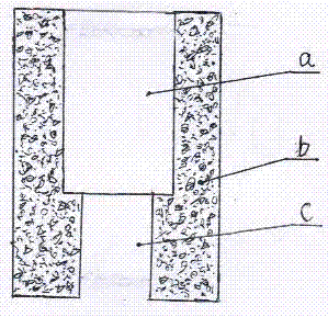
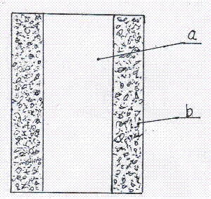
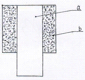
The invention belongs to the construction industry and particularly relates to a stiffening core cement-soil tubular pile, a construction method and a cylindrical rotary stirring drilling tool. According to the structure, a cement-soil tubular pipe body b is longer than a cored pile a, is as long as the cored pile a and is shorter than the cored pile a, and the center of the cement-soil tubular pile is soil. By means of the stiffening core cement-soil tubular pile, the construction method and the cylindrical rotary stirring drilling tool, the diameter of the cylindrical cement-soil pile can be larger. The completed pile with defects and with bearing force not meeting the design requirement can be reinforced through the method, the formed stiffening core cement-soil tubular pile is high in bearing force, uplift resistance and shear resistance, high in construction speed and low in cost, and people do not need to worry that the cored pile can not be inserted in the formed tubular pipe.

Description

technical field [0001] The invention belongs to the construction industry, and in particular relates to a cement-soil tubular pile with a strong core, a construction method and a tubular rotary drilling tool. Background technique [0002] Most of the current core pile construction is to form the outer pile first, and then insert the core pile to form a composite pile, especially when inserting the core pile into the cement soil, sometimes it will be difficult to insert the core because of poor control of the core insertion time. The application date is 2010 On June 2, 2010, the application number was 201010189668.7, and a construction method of composite foundation pile was announced in "Cement Composite Foundation Pile and Construction Method of Core-filled Pipe Pile". Before the initial setting of the cement, the pipe piles are statically pressed and then the core is filled. If the pipe piles are pressed in early, a lot of grout will overflow, and if the pressure is late, ...

Claims


Application Information

Patent Timeline
Patent Type & Authority Patents(China)
IPC IPC(8): E02D5/46E02D5/50E02D15/04
CPCE02D5/46E02D5/50E02D15/04E02D2250/0023
Inventor 王庆伟林红艳王琢璐
Owner 王庆伟
Learn More