A prefabricated shear wall with cast-in-place connection

A connection method, prefabricated shear force technology, applied in the direction of walls, building materials, building components, etc., can solve the problems of insufficient anchorage length of steel bars, difficult to check, weaken the shear resistance of shear walls, etc., to improve the resistance to rainwater penetration. The effect of reducing the workload of the formwork and eliminating the hidden danger of the connection

Active Publication Date: 2018-09-07
HUA HUI ENGINEERING DESIGN GROUP CO LTD
View PDF5 Cites 0 Cited by
  • Summary
  • Abstract
  • Description
  • Claims
  • Application Information

AI Technical Summary

Problems solved by technology

Although the experimental effect of this method in the laboratory can meet the force requirements, there are many problems in reality, and it also leaves many quality problems for the building structure.
If due to prefabrication or construction errors, the upper and lower shear wall steel bars may be misaligned. At this time, it is difficult to insert the lower steel bars into the slurry anchor sleeves. In addition, the connection method of the slurry anchor sleeves requires a certain anchorage length for the upper and lower steel bars. , the steel bar should be placed in the center of the grouting anchor casing, and the grout should be injected from the grouting hole in the lower part of the grouting anchor casing at a constant speed, and flow out from the upper grouting hole; but in the field operation, the anchoring of the steel bar often occurs Insufficient length, steel bars sticking to the casing wall, grouting from top to bottom or rapid grouting, resulting in insufficient grout in the casing, etc. These problems are difficult to check and rework once the construction is completed , leaving permanent quality problems
In addition, the vertical reinforcement of the prefabricated shear wall does not connect up and down, after all, it weakens the shear resistance of the shear wall. At the same time, the bottom of the shear wall is horizontal, which also creates horizontal construction joints, which brings the possibility of water seepage in the later stage.

Method used


Image

  • A prefabricated shear wall with cast-in-place connection
  • A prefabricated shear wall with cast-in-place connection
  • A prefabricated shear wall with cast-in-place connection

Examples


Embodiment Construction

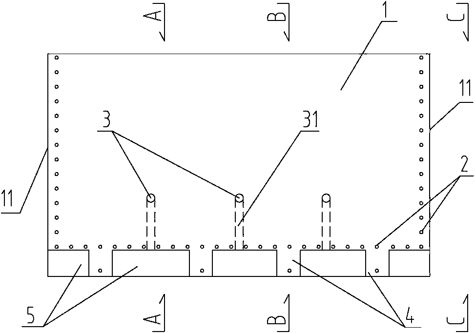
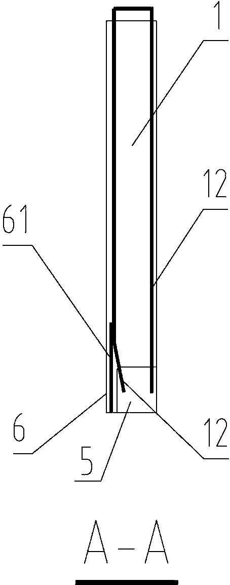
[0023] Please refer to the attached figure 1 to attach Figure 4 As shown, the present invention is a prefabricated shear wall adopting the cast-in-place connection method, which is composed of a wall body 1, a pier head 4, an upper concave section 5 at the bottom, and an outer side plate 6 at the bottom.

[0024] Wherein, the two sides of the wall body 1 are provided with side edges 11 respectively, and a groove 7 is arranged in the middle of each side edge 11 . The groove 7 runs through the wall up and down, which can effectively increase the contact area between the side 11 of the prefabricated wallboard and the cast-in-place part, and can effectively improve the resistance of the connection part between the prefabricated wallboard and the cast-in-place part to resist rainwater penetration during building use .

[0025] Vertical steel bars 12 are arranged inside the wall 1 . The vertical steel bars 12 of the wall do not need to be connected by pre-embedded grout anchor s...


PUM


Abstract

The invention relates to a prefabricated shear wall in a cast-in-situ connection mode. The prefabricated shear wall comprises a wall, pier heads, bottom upper concave sections and a bottom outer side plate. Side edges are respectively arranged on two sides of the wall, and a groove is formed in the middle of each side edge and is vertically perforated through the wall; wall vertical reinforcing bars are arranged in the wall; the bottom upper concave sections are uniformly distributed at the bottom of the wall; each pier head is arranged between the two corresponding adjacent bottom upper concave sections; air holes are formed in positions above the middles of the bottom upper concave sections; the air holes are communicated with the bottom upper concave sections via pipelines; the thicknesses of the pier heads are identical to the thickness of the wall, and holes are formed in the pier heads; the bottom outer side plate and the wall are integrated with each other, and the bottom outer side plate is positioned on the outer sides of the bottom upper concave sections; internally threaded pipes are embedded in positions close to the side edges of the wall, above the bottom upper concave sections and on the pier heads. The prefabricated shear wall in the cast-in-situ connection mode has the diversified advantages of firm structure, convenience in construction, reliability in connection and the like.

Description

【Technical field】 [0001] The invention relates to a shear wall, in particular to a prefabricated shear wall adopting a cast-in-place connection mode, and belongs to the technical field of construction engineering. 【Background technique】 [0002] The industrialization of construction is an inevitable direction for the development of China's construction industry. At present, prefabricated integral shear walls are being promoted in China. The bottom of the prefabricated shear wall is horizontal, and some vertical steel bars are connected with the lower vertical steel bars of the shear wall by pre-embedded grout anchor sleeves, while the rest of the vertical steel bars are not connected at all. Although the experimental results of this approach in the laboratory can meet the force requirements, there are many problems in reality, and it also leaves many quality problems for the building structure. If due to prefabrication or construction errors, the upper and lower shear wall ...

Claims


Application Information

Patent Timeline
Patent Type & Authority Patents(China)
IPC IPC(8): E04B2/00E04C2/30
CPCE04B2/00E04B2103/02E04C2/46
Inventor 肖景平陈威文周卫东张鑫刘泓鑫官尖锋钱一栋
Owner HUA HUI ENGINEERING DESIGN GROUP CO LTD
Why Eureka
Try Eureka