Pull-joint type double-steel-plate composite shear wall

A combined shear wall and double steel plate technology, applied in the direction of walls, buildings, building components, etc., can solve the problems that the mechanical performance is controlled by the welding performance, the welding temperature of the steel plate is affected, and the wall surface is not flat, so as to achieve excellent seismic performance, The effect of welding seam quality is small, and the effect of meeting the requirements of the wall width-thickness ratio

Inactive Publication Date: 2016-05-25
HEFEI UNIV OF TECH +1
View PDF5 Cites 12 Cited by
  • Summary
  • Abstract
  • Description
  • Claims
  • Application Information

AI Technical Summary

Problems solved by technology

This kind of steel plate shear wall forms several cavities through welding connection of a large number of H-shaped, U-shaped, and T-shaped members. Because the weld seam is on the stress-bearing surface, and the thinner steel plate is easily affected by the welding temperature, there are disadvantages such as heavy welding workload, uneven wall surface, and mechanical performance controlled by welding performance.

Method used


Image

  • Pull-joint type double-steel-plate composite shear wall
  • Pull-joint type double-steel-plate composite shear wall
  • Pull-joint type double-steel-plate composite shear wall

Examples


Embodiment 1

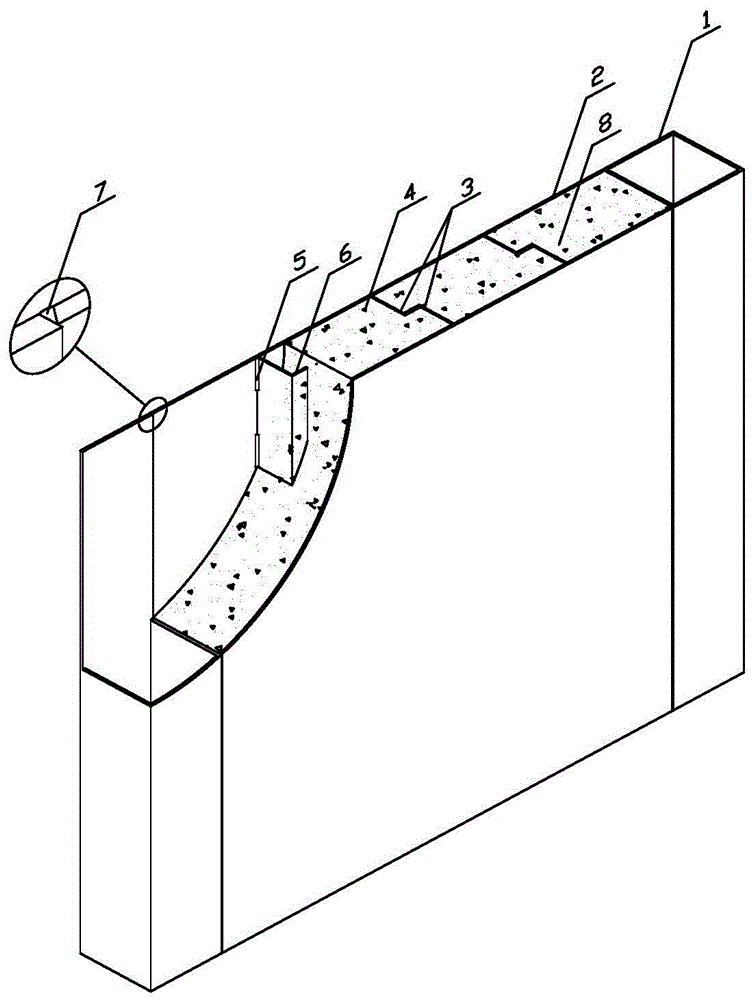
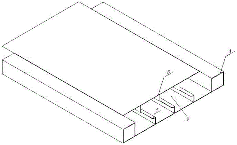
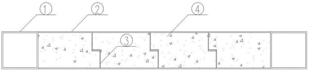
[0033] Please refer to Figure 1-6 , the present invention provides a tie-type double-steel composite shear wall, which includes a steel pipe column 1 located at both ends, a pair of steel plates 2 and at least one tie-type connector 3, and the two steel plates 2 pass through the tie-type connector 3 The knots form a whole. The tie-type connector 3 divides the cavity between the two steel plates 2 into at least two tubular cavities 8. Concrete 4 is poured in the tubular cavities 8, and concrete is poured between the double steel plate wall panels. The end steel pipe columns are poured or not concreted according to the needs; compared with the traditional concrete shear wall, the tie-type double-steel plate composite shear wall has high bearing capacity, good ductility, strong energy dissipation capacity, excellent seismic performance, and does not require support. Compared with other double-steel plate composite shear walls, the tie-type connectors are firstly welded and conne...

Embodiment 2

[0044] Please refer to Figure 5 , preferably, the rest of the structure and manufacturing method are the same as in Embodiment 1, the cross section of the branch connector 6 is a hook type, and the angle between the bent part and the straight rod part of the hook-shaped branch connector 6 is 0°, which is It is easy to assemble, and the bending radius is not less than twice the thickness of the connector. The draw-knot position of every pair of crotch-type branch connectors 6 is located in the middle or edge of the combined wall thickness.

Embodiment 3

[0046] Please refer to Figure 6 , Preferably, the rest of the structure and manufacturing method are the same as in Embodiment 1, and the cross section of the branch connector 6 is sickle-hook type. Please refer to figure 1 , preferably, the angle between the bent portion and the straight rod portion of the hook-shaped branch connector 6 is not greater than 60°. The knot position of each pair of sickle-hook type branch connectors 6 is located in the middle or edge of the combined wall thickness.


PUM


Abstract

The invention discloses a pull-joint type double-steel-plate composite shear wall, comprising steel pipe columns (steel pipe columns or concrete-filled steel tube columns) respectively arranged at the two ends, a pair of steel plates and at least one pull-joint type connecting piece. The pull-joint type connecting piece is firstly connected with the steel plates by staggered and intermittent one-side fillet welds in a welding way, and then a whole is assembled; the pull-joint type double-steel-plate composite shear wall has the advantages that the composite shear wall is simple in pull-joint structure, has a flat wall surface, and is less in welding workload, easy to operate and convenient to assemble; the stress performance of the composite shear wall is seldom affected by the welding quality since weld joints are positioned at construction parts; the composite shear wall is economical and safe; the steel plates and concrete are strong in cooperative work capability. A straight hook L shape, a sickle hook shape or hump hook shape can be adopted as the pull-joint way of the connecting piece, the pull-joint position can be positioned at the middle or side part of the thickness of the composite wall, and the pull-joint way is flexible and changeable, so that different engineering stress and use requirements are met. Riffled plates can be used as the wallboard steel plates and the pull-joint type connecting piece, so that the binding action between the wall steel plates and the concrete is effectively improved, and the co-working between steel components and the concrete is guaranteed.

Description

technical field [0001] The invention relates to the technical field of building structures, in particular to a tie-type double steel plate combined shear wall. Background technique [0002] The double-steel composite shear wall has high bearing capacity, good ductility and stable hysteretic performance. Compared with the traditional concrete shear wall, it does not require formwork. The construction speed is fast and the wall is thin, which can effectively reduce the The structure is self-respecting. [0003] The double-steel composite shear walls that have been used at present generally include double-steel composite shear walls with tension bolts on both sides, double-steel composite shear walls with studs or T-shaped stiffeners on the inside of the wall panels, etc., such walls The thickness of the steel plate is relatively thick due to the way of tie, generally not less than 10mm, and the economy is poor. And the double-steel composite shear wall with tension bolts on ...

Claims


Application Information

Patent Timeline
Patent Type & Authority Applications(China)
IPC IPC(8): E04B2/58E04B2/68
CPCE04B2/58E04B2/68
Inventor 陈丽华夏登荣蒯从伦阮海燕刘文武杨柳
Owner HEFEI UNIV OF TECH
Why Eureka
Try Eureka