Centrifugal pump impeller sealing structure

A centrifugal pump impeller, centrifugal wheel technology, applied in the direction of pumps, pump components, non-variable-capacity pumps, etc., can solve the problems of improving pump efficiency, poor sealing effect, friction power consumption of front and rear bosses, etc., to achieve stability and structure. High reliability, stable leakage cooling flow, and the effect of reducing the contact area

Inactive Publication Date: 2016-05-25
XIAN AEROSPACE PROPULSION INST
View PDF8 Cites 4 Cited by
  • Summary
  • Abstract
  • Description
  • Claims
  • Application Information

AI Technical Summary

Problems solved by technology

[0003] ① The turbine of the upper stage engine is small in size and compact in structure, and the front and rear seals of the pump impeller with floating ring seal structure are relatively complex and have many parts, which is not conducive to design and layout in a narrow space
[0004] ②Floating ring structure seal, although the efficiency is high under the same gap, but it is limited by the structure, it is not suitable for use in a small sealing gap, so that the volume loss cannot be further reduced to improve the pump efficiency, and the floating effect of the floating ring is likely to be poor. Good, friction and power consumption will occur with the front and rear bosses of the pump wheel, and wear will occur in severe cases, which will affect the reliability and stability of the engine work
[0005] ③For the small-flow and high-speed pump of the upper stage, the leakage before and after the pump wheel is small, and the sealing effect of the floating ring is poor, and the leakage control is unstable
Especially when the engine starts, due to its fast start-up acceleration, and the pressure in the pump has not been fully established during the pump wheel spin-up process, the medium flow rate before and after entering the pump is very small, which is not enough to ensure the smooth floating operation of the floating ring structure, which is very easy Causes friction between the floating ring and the sealing boss of the pump wheel, resulting in additional power consumption and affecting the performance of the pump

Method used


Image

  • Centrifugal pump impeller sealing structure
  • Centrifugal pump impeller sealing structure

Examples


Embodiment Construction

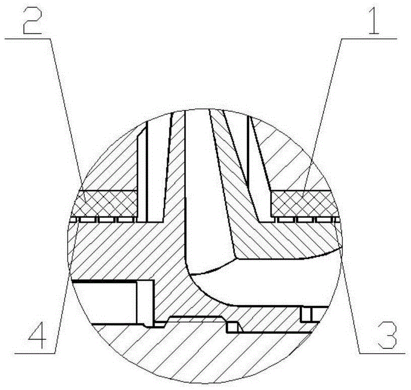
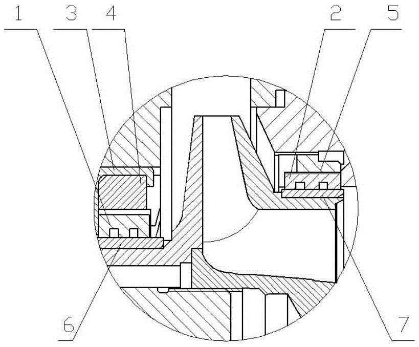
[0019] For the low specific speed centrifugal pump with small flow rate and high speed, its hydraulic efficiency is low under the ideal state. Therefore, in order to ensure the efficiency close to the ideal state, the influence of volume loss must be strictly controlled. Reducing the leakage gap before and after the centrifugal pump is the most direct means to improve the volumetric efficiency, but too small sealing gap will easily cause the pump running process, and the friction between the pump impeller and the sealing ring will occur under the action of the shafting beating, resulting in additional power consumption and fluctuations in working conditions. The invention solves the contradiction between improving the hydraulic efficiency and the friction between the pump wheel and the sealing ring under a small gap. The graphite sealing ring is embedded on the pump casing, and the sealing teeth are respectively processed on the front boss and the rear boss of the centrifugal ...


PUM


Abstract

The invention provides a centrifugal pump impeller sealing structure. The centrifugal pump impeller sealing structure comprises a centrifugal impeller front lug boss sealing gear, a centrifugal impeller back lug boss sealing gear and two graphite sealing rings, the centrifugal impeller front lug boss sealing gear and the centrifugal impeller back lug boss sealing gear are integrally machined on a centrifugal pump impeller base body matrix respectively; the two graphite sealing rings correspond to the centrifugal impeller front lug boss sealing gear and the centrifugal impeller back lug boss sealing gear respectively and are inlaid onto a pump shell. The centrifugal pump impeller sealing structure is applicable to a small-flow and high-rotation speed centrifugal pump; the centrifugal pump impeller sealing structure can achieve effective control of leakage by selecting a small sealing gap, does not increase the power loss and effectively improves the pump efficiency; compared with the conventional floating ring seal, the centrifugal pump impeller sealing structure has the advantage that in the starting process and in the stable working process, leaking cooling flow is relatively fixed, so that the working stability of the pump is effectively improved; besides, the centrifugal pump impeller sealing structure is compact, simple and reliable, and is especially applicable to design requirements of a small-sized light-weighted pump.

Description

technical field [0001] The invention belongs to a labyrinth sealing structure of a centrifugal pump wheel of a liquid rocket engine. The sealing structure has the advantages of compact and simple structure, which can be used in small gaps and can strictly control the leakage cooling flow rate of the centrifugal pump. Especially suitable for small flow, high efficiency, high speed liquid rocket engine centrifugal pumps. Background technique [0002] According to the current development needs of my country's space launch missions, the upper-stage rocket engine requires turbo pumps with high performance and light weight, so it is necessary to ensure that the centrifugal pumps used have high efficiency and stability. The volume loss control of the centrifugal wheel of the liquid rocket engine usually adopts the labyrinth seal structure of the metal floating ring seal structure. The current research believes that, compared with the fixed labyrinth seal, under the same clearance c...

Claims


Application Information

Patent Timeline
Patent Type & Authority Applications(China)
IPC IPC(8): F04D29/16
CPCF04D29/167
Inventor 徐楠安莎赵瑞勇张晶辉刘军年白东安张翠儒毋杰杨大昱
Owner XIAN AEROSPACE PROPULSION INST
Why Eureka
Try Eureka