Self-driven low-level-energy heat pump with function of automatic condensate recovery and air conditioning system

A technology of automatic recovery and air conditioning system, applied in the field of heat pump and refrigeration equipment, it can solve the problems of high maintenance rate atmospheric environment, easy refrigerant leakage, etc., achieve independent operation control, reduce maintenance workload, and save condensate water discharge system. Effect

Inactive Publication Date: 2016-05-25
陈昀
View PDF8 Cites 2 Cited by
  • Summary
  • Abstract
  • Description
  • Claims
  • Application Information

AI Technical Summary

Problems solved by technology

Due to the inherent characteristics of the split air conditioner, compared with the integrated air conditioner such as the window type, it nat

Method used


Image

  • Self-driven low-level-energy heat pump with function of automatic condensate recovery and air conditioning system
  • Self-driven low-level-energy heat pump with function of automatic condensate recovery and air conditioning system

Examples


Embodiment 1

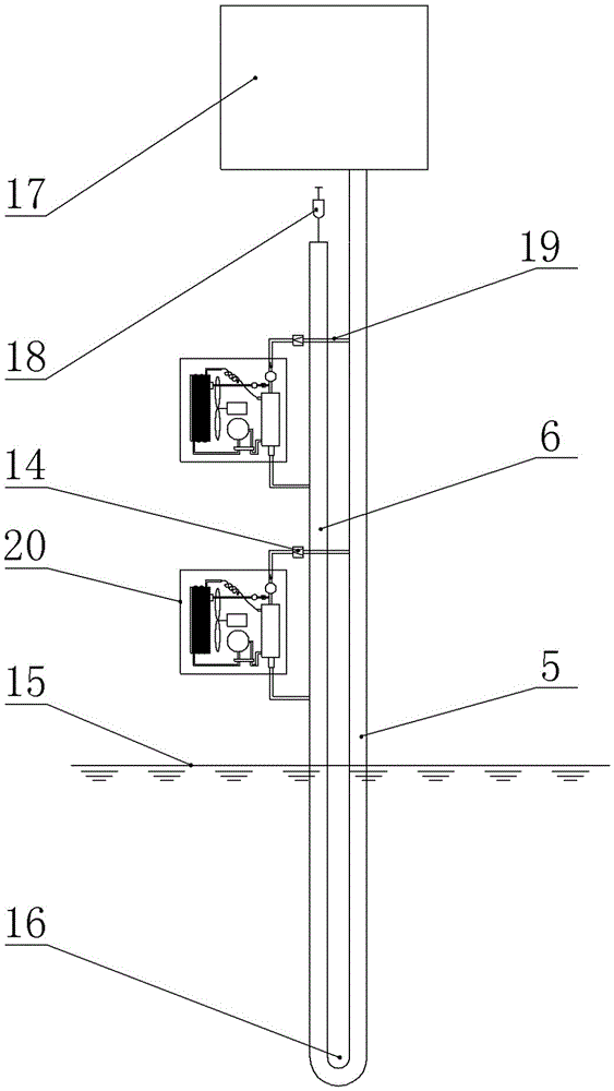
[0022] Embodiment one: see figure 1 and figure 2 , a self-driven low-level energy heat pump and air-conditioning system with the function of automatic recovery of condensed water, including a heat pump air-conditioning system 20, a low-level energy liquid system and a control system, wherein the low-level energy extraction object is ground source energy, and the The heat pump air-conditioning system 20 includes a finned tube heat exchanger 1, a compressor 2, a shell and tube heat exchanger 3 and a capillary tube 4 connected in sequence; Pipeline 5 and water return pipeline 6, the upper end of the water supply pipeline is higher than the upper end of the return water pipeline, and a low energy heat exchanger 16 is communicated between the water supply pipeline 5 and the lower end of the return water pipeline 6. The top of the water supply pipeline 5 is provided with an expansion tank 17 , and the top of the return water pipeline 6 is provided with an automatic emptying valve ...

Embodiment 2

[0029]Embodiment 2: The structure of this embodiment is basically the same as that of Embodiment 1, and the similarities will not be repeated. The difference is that the low-level energy access objects are urban sewage, industrial and domestic residual temperature hot water, or For seawater, the low potential energy liquid system includes a water supply pipeline and a return water pipeline in which the lower part is arranged in the low potential energy extraction object, and a low potential energy heat exchange is arranged between the water supply pipeline and the lower end of the return water pipeline An expansion tank is installed on the top of the water supply pipeline, and an automatic emptying valve is installed on the top of the return water pipeline.

[0030] At the same time, for different low-level energy application objects, corresponding reasonable changes should be made to the system according to the nature of the application objects. For example, in low-level energ...


PUM


Abstract

The invention belongs to the technical field of refrigeration equipment and heat pumps and discloses a self-driven low-level-energy heat pump with a function of automatic condensate recovery and an air conditioning system. The air conditioning system comprises a heat pump air conditioning system, a low-level-energy liquid system and a control system. The heat pump air conditioning system comprises a finned tube exchanger, a compressor, a shell-and-tube heat exchanger and a capillary in sequentially loop connection, and a low-level-energy liquid drive pump and a check valve are arranged between a tube pass of the shell-and-tube heat exchanger and a water supply pipeline. A four-way reversing valve is arranged between two ends of the compressor, and a fan is arranged on the lateral side of the finned tube exchanger along with a condensate collection tray and a condensate collection groove. The condensate collection groove is connectedly provided with a condensate delivery pump and a check valve through a condensate delivery pipeline. Operating efficiency uniformity in full-load operation and arbitrary low-load operation of the system is realized, the defect of failure in operation due to the fact that the lowest operation load of the system is higher than an actually demanded load is eliminated, and full-load operation and low-load operation are balanced.

Description

technical field [0001] The invention belongs to the technical field of refrigeration equipment and heat pumps, and in particular relates to a self-driven low-energy heat pump and an air-conditioning system with the function of automatically recovering condensed water. Background technique [0002] As the world pays more and more attention to the greenhouse effect of the earth's environment, the need to apply related technologies to achieve energy saving and emission reduction is becoming more and more urgent. In this environment, research on how to effectively utilize low-level energy technologies such as ground sources, sewage sources, and seawater sources is in the ascendant. Driven by this wave, specific applications using low-level energy such as ground source heat pumps and air conditioners are becoming more and more widespread. [0003] At present, the field of low-level energy utilization tends to concentrate cooling and heating in practice. Although this utilizatio...

Claims


Application Information

Patent Timeline
IPC IPC(8): F24F5/00F24F13/22F24F11/02F25B30/06F25B13/00
CPCY02B30/52F24F5/001F24F5/0046F24F11/89F24F13/222F25B13/00F25B30/06F25B2313/02741
Inventor 陈昀
Owner 陈昀
Why Eureka
Try Eureka