Grid driving circuit and liquid crystal display apparatus

A gate drive circuit and gate drive technology, applied in static indicators, instruments, etc., can solve the problems of frame drop, affect the display effect, reduce the performance of the graphics card, etc., and achieve the effect of avoiding tearing and improving the display quality

Active Publication Date: 2016-05-25
KUSN INFOVISION OPTOELECTRONICS
View PDF5 Cites 6 Cited by
  • Summary
  • Abstract
  • Description
  • Claims
  • Application Information

AI Technical Summary

Problems solved by technology

However, if the vertical synchronization function of the graphics card is turned on, the performance of the

Method used


Image

  • Grid driving circuit and liquid crystal display apparatus
  • Grid driving circuit and liquid crystal display apparatus
  • Grid driving circuit and liquid crystal display apparatus

Examples


no. 1 example

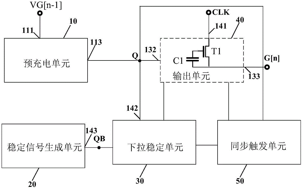
[0033] figure 2 is a circuit diagram of the gate drive unit circuit provided by the first embodiment of the present invention. see figure 2 , The gate driving unit circuit 5 includes: a pre-charging unit 10 , a stable signal generating unit 20 , a pull-down stabilizing unit 30 , an output unit 40 and a synchronous trigger unit 50 . The pre-charging unit 10 is electrically connected to the pull-down stabilization unit 30 , the output unit 40 , and the synchronization trigger unit 50 , and the pull-down stabilization unit 30 is also electrically connected to the stabilization signal generation unit 20 and the synchronization trigger unit 50 .

[0034] In the embodiments of the present invention, it is assumed that the current gate driving unit circuit is the nth-level gate driving unit circuit, and VG[n] and VC[n] respectively represent the gate scanning signals output by the n-level gate driving unit circuit and transmission signal, VG[n+1], VC[n+1] represent the gate scann...

no. 2 example

[0052] Figure 4 is a circuit diagram of the gate drive unit circuit provided by the second embodiment of the present invention. This embodiment and figure 2 The difference is that: the synchronous trigger unit 50 includes transistors T2 (second transistor) and T3 (third transistor). the rest with figure 2 The gate driving unit circuits shown are the same and will not be repeated here.

[0053] Wherein, the gate of the transistor T2 (second transistor) receives the trigger signal Triggersignal, the first terminal of the transistor T2 (second transistor) is electrically connected to the first voltage output terminal VGL, and the second terminal of the transistor T2 (second transistor) is electrically connected to It is connected to the gate scanning signal output terminal 133 for outputting the gate scanning signal VG[n]. The gate of the transistor T3 receives the trigger signal Triggersignal, the first terminal of the transistor T3 is electrically connected to the first ...

no. 3 example

[0056] Figure 5 is a circuit diagram of the gate drive unit circuit provided by the third embodiment of the present invention. This embodiment and figure 2 The difference is that the synchronous trigger unit 50 includes a transistor T4 (a fourth transistor). the rest with figure 2 The gate driving unit circuits shown are the same and will not be repeated here.

[0057] Wherein, the gate and the first terminal of the transistor T4 receive the trigger signal Triggersignal, and the second terminal of the transistor T4 is electrically connected to the first node QB.

[0058] In this embodiment, when the trigger signal Triggersignal becomes high level, the first node QB is high level, and the pull-down stabilization unit 30 is turned on to pull down the control node Q and the gate scanning signal output terminal 133, so that the current row reaches the end Both the control node Q of the row and the gate scan signal output terminal 133 will be pulled down to low level, and al...


PUM


Abstract

The embodiments of the invention disclose a grid driving circuit and a liquid crystal display apparatus. The grid driving circuit comprises multiple grid driving unit circuits, a clock signal line and a trigger signal line. Each grid driving unit circuit comprises a precharge unit, a stable signal generation unit, a pull-down stable unit, an output unit and a synchronous trigger unit. When a video card sends a new frame of an image to the T-con of a liquid crystal display apparatus, the initial end of the new frame of the image carries vertical synchronization signals, the T-com, after generating trigger signals according to the vertical synchronization signals, providing the trigger signals to the synchronous trigger units, and when the synchronous trigger units receive the trigger signals, control nodes and grid scanning signals which currently travel to a tail-end row are pulled down to low level in a forced mode. The grid driving circuit and the liquid crystal display apparatus can eliminate an image tearing phenomenon and improve the display quality.

Description

technical field [0001] The invention relates to the field of display technology, in particular to a gate drive circuit and a liquid crystal display device. Background technique [0002] Liquid crystal display (Liquid Crystal Display, LCD) has the advantages of good image quality, small size, light weight, low driving voltage, low power consumption, no radiation and relatively low manufacturing cost, and currently occupies a dominant position in the field of flat panel display. Liquid crystal display devices are very suitable for application in various office automation and audio-visual equipment such as desktop computers, palmtop computers, personal digital assistants (Personal Digital Assistant, PDA), portable phones, and television boxes. [0003] Figure 1A It is a schematic diagram of a display screen of an existing liquid crystal display device, such as Figure 1A As shown, the graphics card writes one frame of picture data 2 into the frame buffer 4 at a time, and the f...

Claims


Application Information

Patent Timeline
IPC IPC(8): G09G3/36
CPCG09G3/3674
Inventor 于子阳黎倩
Owner KUSN INFOVISION OPTOELECTRONICS
Why Eureka
Try Eureka