Gate drive circuit and liquid crystal display device
A gate drive circuit and gate drive technology, applied in static indicators, instruments, etc., can solve problems such as frame drop, affect display effect, freeze, etc., and achieve the effect of avoiding tearing and improving display quality
- Summary
- Abstract
- Description
- Claims
- Application Information
AI Technical Summary
Problems solved by technology
Method used
Image
Examples
no. 1 example
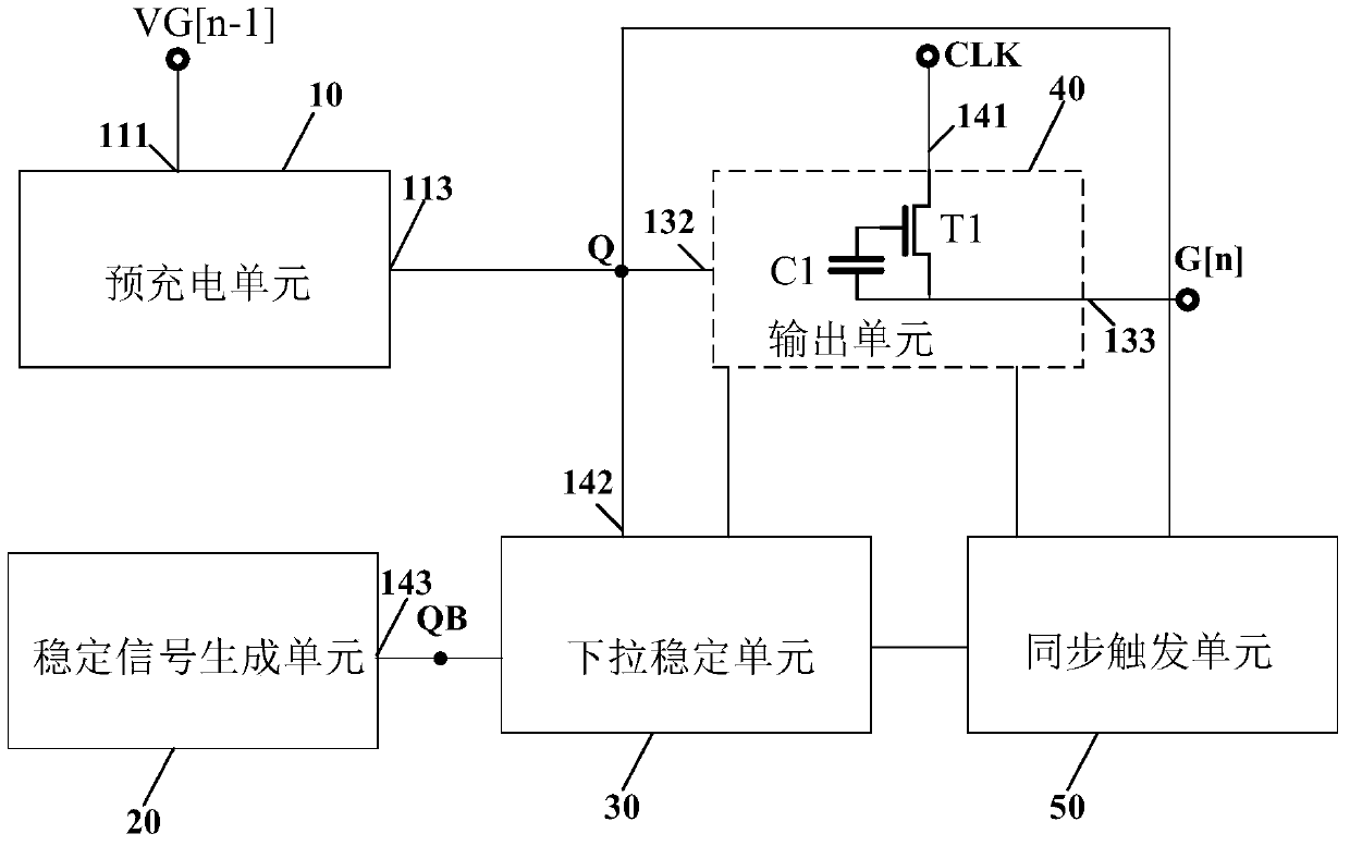
[0033] figure 2 is a circuit diagram of the gate drive unit circuit provided by the first embodiment of the present invention. see figure 2 , The gate driving unit circuit 5 includes: a pre-charging unit 10 , a stable signal generating unit 20 , a pull-down stabilizing unit 30 , an output unit 40 and a synchronous trigger unit 50 . The pre-charging unit 10 is electrically connected to the pull-down stabilization unit 30 , the output unit 40 , and the synchronization trigger unit 50 , and the pull-down stabilization unit 30 is also electrically connected to the stabilization signal generation unit 20 and the synchronization trigger unit 50 .
[0034] In the embodiments of the present invention, it is assumed that the current gate driving unit circuit is the nth-level gate driving unit circuit, and VG[n] and VC[n] respectively represent the gate scanning signals output by the n-level gate driving unit circuit and transmission signal, VG[n+1], VC[n+1] represent the gate scann...
no. 2 example
[0052] Figure 4 is a circuit diagram of the gate drive unit circuit provided by the second embodiment of the present invention. This embodiment and figure 2 The difference is that: the synchronous trigger unit 50 includes transistors T2 (second transistor) and T3 (third transistor). the rest with figure 2 The gate driving unit circuits shown are the same and will not be repeated here.
[0053] Wherein, the gate of the transistor T2 (second transistor) receives the trigger signal Trigger signal, the first terminal of the transistor T2 (second transistor) is electrically connected to the first voltage output terminal VGL, and the second terminal of the transistor T2 (second transistor) Electrically connected to the gate scan signal output terminal 133 for outputting the gate scan signal VG[n]. The gate of the transistor T3 receives a trigger signal, the first terminal of the transistor T3 is electrically connected to the first voltage output terminal VGL, and the second t...
no. 3 example
[0056] Figure 5 is a circuit diagram of the gate drive unit circuit provided by the third embodiment of the present invention. This embodiment and figure 2 The difference is that the synchronous trigger unit 50 includes a transistor T4 (a fourth transistor). the rest with figure 2 The gate driving unit circuits shown are the same and will not be repeated here.
[0057] Wherein, the gate and the first end of the transistor T4 receive a trigger signal, and the second end of the transistor T4 is electrically connected to the first node QB.
[0058] In this embodiment, when the trigger signal Trigger signal becomes high level, the first node QB is high level, and the pull-down stabilization unit 30 is turned on to pull down the control node Q and the gate scanning signal output terminal 133, so that the current row to Both the control node Q and the gate scanning signal output terminal 133 of the last row will be pulled down to low level, and all the gate lines from the cur...
PUM
 Abstract
Description
Claims
Application Information
 - R&D
- Intellectual Property
- Life Sciences
- Materials
- Tech Scout
- Unparalleled Data Quality
- Higher Quality Content
- 60% Fewer Hallucinations
Browse by: Latest US Patents, China's latest patents, Technical Efficacy Thesaurus, Application Domain, Technology Topic, Popular Technical Reports.
© 2025 PatSnap. All rights reserved.Legal|Privacy policy|Modern Slavery Act Transparency Statement|Sitemap|About US| Contact US: help@patsnap.com


