Hybrid DC current breaker topological structure

A technology of DC circuit breaker and topology structure, applied in circuits, circuit devices, emergency protection circuit devices, etc., can solve the problems of low loss, short breaking time, unable to guarantee 100% solid-state switch conduction and complete commutation, etc. , to achieve the effect of low loss and short breaking time

Active Publication Date: 2016-05-25
STATE GRID TIANJIN ELECTRIC POWER +1
View PDF8 Cites 33 Cited by
  • Summary
  • Abstract
  • Description
  • Claims
  • Application Information

AI Technical Summary

Problems solved by technology

However, in practical applications, due to the lack of practical and reliable DC circuit breakers, it is difficult to clear the DC side short-circuit faults of the flexible DC distribution network in time, resulting in great restrictions on its development.
[0003] At present, the development of DC circuit breakers mainly faces the following difficulties: (1) DC current does not have a natural zero-crossing point, and it is difficult to extinguish the DC arc; (2) After the current is cut off, a high recovery overvoltage will be generated at both ends of the circuit breaker; (3) The energy stored in the system inductance needs to be released after the current is cut off; (4) Applications such as DC transmission and distribution networks require short break time
[0004] Commonly used DC circuit breakers include

Method used


Image

  • Hybrid DC current breaker topological structure
  • Hybrid DC current breaker topological structure
  • Hybrid DC current breaker topological structure

Examples


Embodiment Construction

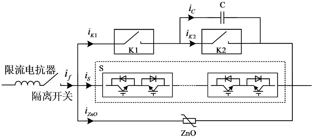
[0019] A hybrid DC circuit breaker topology such as figure 1 As shown, it includes a current-limiting reactor, an isolating switch and three parallel branches; one end of the current-limiting reactor is connected to one end of the isolating switch, and the other end of the isolating switch is connected to the three parallel branches. One end is connected in series; among the three parallel branches, the first branch is composed of a first mechanical switch K1, a second mechanical switch K2 and a capacitor C, the first mechanical switch K1 and the second mechanical switch K2 are connected in series, and the second mechanical switch The switch K2 is connected in parallel with the capacitor C, and is used to conduct the normal working current of the system; the above-mentioned first mechanical switch K1 and the second mechanical switch K2 are ultra-fast mechanical switches; the second branch is a solid-state switch S, and the solid-state switch S is composed of A number of IGBT m...


PUM


Abstract

The invention relates to a hybrid DC current breaker topological structure. The hybrid DC current breaker topological structure is structurally characterized by comprising three parallel branches, wherein the first branch comprises a first mechanical switch K1, a second mechanical switch K2 and a capacitor C; the first mechanical switch K1 and the second mechanical switch K2 are connected in series and the second mechanical switch K2 and the capacitor C are connected in parallel, so as to get continuity of the normal working current of a system; the second branch is a solid-state switch S which is composed of a plurality of IGBT modules connected in series, wherein each IGBT module comprises two IGBTs in reversed series connection and is used for realizing two-way cutoff of fault current; the third branch is an energy release branch consisting of multiple ZnO lightning arresters in series and parallel connection. The hybrid DC current breaker disclosed by the invention has the advantages of low loss, achievement of two-way rapid cutoff and guarantee of reliable continuity of the solid-state switch.

Description

technical field [0001] The invention belongs to the technical field of direct current circuit breakers, and in particular relates to a topology structure of a hybrid direct current circuit breaker. Background technique [0002] At present, the flexible DC distribution network has significant technical and economic advantages compared with the traditional AC distribution network in terms of increasing the power supply radius and capacity, reducing line costs, facilitating distributed power access, and improving system efficiency. However, in practical applications, due to the lack of practical and reliable DC circuit breakers, it is difficult to clear the short-circuit faults on the DC side of the flexible DC distribution network in time, which has greatly restricted its development. [0003] At present, the development of DC circuit breakers mainly faces the following difficulties: (1) DC current does not have a natural zero-crossing point, and it is difficult to extinguish ...

Claims


Application Information

Patent Timeline
IPC IPC(8): H01H9/54
CPCH02H3/087
Inventor 宋光举孙振于啸张晶赵润泽刘伟
Owner STATE GRID TIANJIN ELECTRIC POWER
Why Eureka
Try Eureka