Integrated heat sink based on metal phase-change material and heat pipes

A technology of metal phase change and phase change materials, which is applied in the direction of cooling/ventilation/heating transformation, electrical components, and structural parts of electrical equipment, etc., to achieve the effects of simplifying the structure, strengthening conduction, and prolonging the action time

Inactive Publication Date: 2016-05-25
TSINGHUA UNIV
View PDF4 Cites 21 Cited by
  • Summary
  • Abstract
  • Description
  • Claims
  • Application Information

AI Technical Summary

Problems solved by technology

And these extreme heat dissipation problems, a single p

Method used


Image

  • Integrated heat sink based on metal phase-change material and heat pipes
  • Integrated heat sink based on metal phase-change material and heat pipes
  • Integrated heat sink based on metal phase-change material and heat pipes

Examples


Embodiment 1

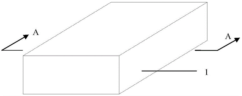
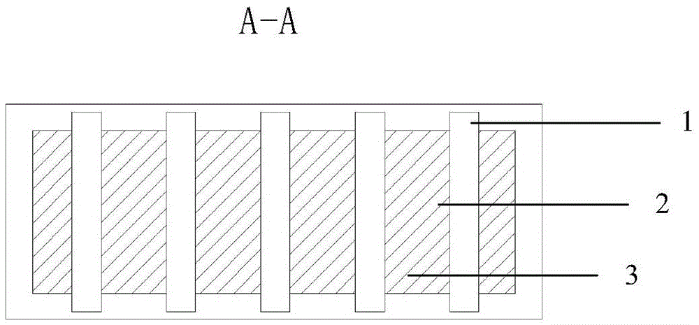
[0041] Embodiment 1 of the present invention is an integrated radiator in the form of a flat plate, and its specific structure is as follows: figure 1 with figure 2 As shown, it includes a cavity 1, a phase change material 2 and five heat pipes 3, the phase change material and heat pipes are packaged in the cavity, the end of the heat pipe is buried in the cavity, and the heat release end is inserted between the phase change materials middle;

[0042] The appearance of the cavity 1 in this embodiment is a flat rectangle, made of nickel, stainless steel or graphite.

[0043] The phase-change material 2 of this embodiment is any of gallium, gallium-indium alloy, bismuth-indium-tin alloy, and other low-melting-point alloys prepared with gallium and / or bismuth and / or indium as basic metals. The interior space is completely filled.

[0044] The heat pipe of this embodiment adopts conventional heat pipe products that match the size of the cavity (for example, for the heat dissip...

Embodiment 2

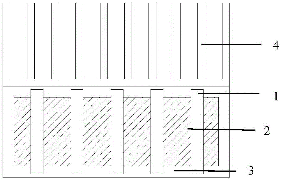
[0047] The concrete structure of present embodiment 2 is as image 3 As shown, in this embodiment, on the basis of the structure of the above-mentioned embodiment 1, cooling fins 4 are installed on the outer side of the cavity. The cooling fins can be conventional products whose size matches the cavity. The surface on the outer side of the cavity is bonded. The heat of this structural heat source is absorbed by the phase change material on the one hand, and on the other hand, is transferred from the heat pipe to the external heat dissipation fins, and is dissipated from the fins to the environment, so as to reduce the heat dissipation load of the phase change material and prolong its action time. The rest of the structure and working principle are exactly the same as that of Embodiment 1.

Embodiment 3

[0049] The concrete structure of present embodiment 3 is as Figure 4 As shown, heat dissipation fins 4 are installed on the outside of the heat pipe on the structure of embodiment 2: for example, 1 mm thickness, 5 cm length, and 3 cm width sheet are used to make them with a spacing of 8 mm, and five fins 31 are installed on each heat pipe 3 ; Installing fins on the heat pipe can further strengthen the heat exchange between the heat pipe and the phase change material, and can reduce the number of heat pipes used. The rest of the structure and working principle are exactly the same as the basic structure of Embodiment 1.


PUM

PropertyMeasurementUnit
The inside diameter ofaaaaaaaaaa
Lengthaaaaaaaaaa

Abstract

The invention provides an integrated heat sink based on a metal phase-change material and heat pipes, belonging to the technical field of a heat sink. The integrated heat sink comprises cavity, a phase-change material and one or more than two heat pipes, wherein the phase-change material and the heat pipes are embedded together and packaged in the cavity, heat absorption ends of the heat pipes are exposed out of the wall of the cavity or buried in the cavity, and heat discharge ends of the heat pipes are inserted into the phase-change material. In the integrated heat sink, the heat absorption characteristic of the metal phase-change material and the high-efficiency heat conduction capability of the heat pipes are fully utilized, the heat from a heat source end is rapidly transferred to the interior of the whole phase-change material, and the defects that the heat conductivity of a traditional metal phase-change material is low and a pure heat pipe is difficult to stand high heat flux density are overcome; and two cooling modes are combined and are supplementary, respective advantages of the two cooling modes are developed, the defects are made up by each other, more severe cooling demand and a working environment can be dealt with, and the integrated heat sink has the capability of dealing with heat flux impact and is a high-efficiency, energy-saving and reliable cooling mode.

Description

technical field [0001] The invention belongs to the technical field of radiators, in particular to an integrated radiator with high latent heat absorption capacity and high thermal conductivity based on metal phase-change materials and heat pipes for heat exchange. Background technique [0002] With the rapid development of electronic technology, the functions of electronic products are becoming more and more perfect, and the degree of integration of corresponding circuits is also getting higher and higher. Electronic components will inevitably generate heat during use. If the heat cannot be dissipated in time, the temperature of electronic components will rise. Miniaturization, multi-function and integration make the problem of "thermal barrier" of electronic products increasingly prominent. Excessive temperature will reduce the efficiency, stability and life of electronic products, and even cause failure, fire and explosion. Therefore, effective thermal management techni...

Claims


Application Information

Patent Timeline
IPC IPC(8): H05K7/20
CPCH05K7/20336H05K7/20
Inventor 何志祝杨小虎刘静
Owner TSINGHUA UNIV
Why Eureka
Try Eureka