Rotary location type gear shaft gear tooth end chamfering grinding processing device

A grinding process, gear shaft technology, applied in the direction of metal processing equipment, gear tooth manufacturing equipment, gear teeth, etc., can solve the problems of increasing the burden of gear processing costs for enterprises, difficult to equip small and medium-sized enterprises, and expensive milling machines, etc., to achieve simple structure , The grinding wheel loss is small, and the effect of easy production

Inactive Publication Date: 2016-06-01
綦江县飞达重型汽车齿轮厂
View PDF9 Cites 5 Cited by
  • Summary
  • Abstract
  • Description
  • Claims
  • Application Information

AI Technical Summary

Problems solved by technology

Although the method of milling can meet the needs of chamfering at the end of the gear shaft, the special milling machine is expensive, and it is difficult for small and medium-sized enterprises to equip it.
In addition, the loss of the milling cutter is also relatively large, which undoubtedly increases the processing cost of the gear and the burden on the enterprise

Method used


Image

  • Rotary location type gear shaft gear tooth end chamfering grinding processing device
  • Rotary location type gear shaft gear tooth end chamfering grinding processing device
  • Rotary location type gear shaft gear tooth end chamfering grinding processing device

Examples


Embodiment Construction

[0031] The present invention will be further described below in conjunction with the accompanying drawings and specific embodiments, so that those skilled in the art can better understand the present invention and implement it, but the examples given are not intended to limit the present invention.

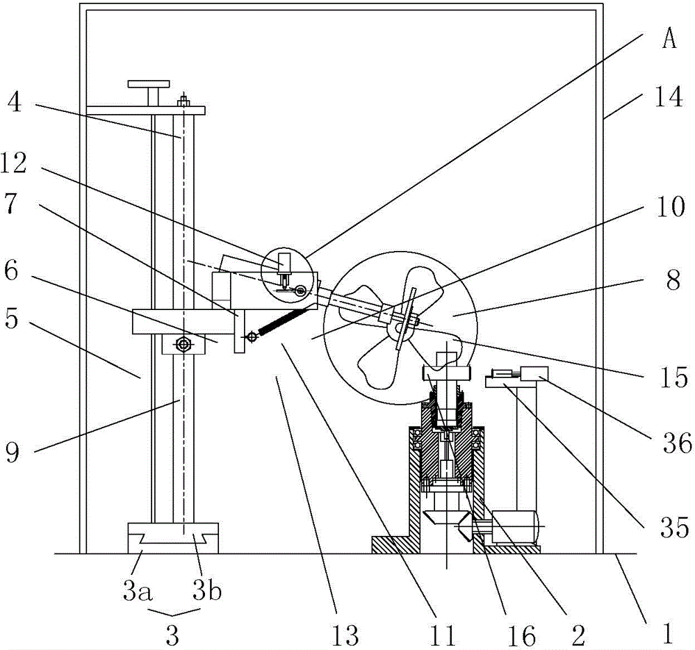
[0032] Such as figure 1 As shown, it is a structural schematic diagram of an embodiment of the equipment for chamfering and grinding the ends of teeth of a rotary positioning gear shaft according to the present invention. The rotary positioning type gear shaft tooth end chamfering grinding processing equipment of this embodiment includes a workbench 1 on which a grinding wheel installation and adjustment tool and a gear clamping tool 2 are arranged.

[0033] The grinding wheel installation and adjustment tooling includes a base 3, the base 3 is provided with a vertical guide rod 4, and the guide rod 4 is provided with a sliding seat 5 which is fitted with a sliding fit, and the sl...


PUM


Abstract

The invention discloses a rotary location type gear shaft gear tooth end chamfering grinding processing device which comprises a workbench, wherein a grinding wheel mounting and adjusting tooling and a gear clamping tooling are arranged on the workbench; the grinding wheel mounting and adjusting tooling comprises a base; vertical guide rods are arranged on the base; a sliding seat is arranged on the guide rods; a grinding wheel mounting seat is arranged on the sliding seat; a grinding wheel mechanism is mounted on the grinding wheel mounting seat; the grinding wheel mechanism comprises a pneumatic motor and a grinding wheel mounted on a rotating shaft of the pneumatic motor; a locking mechanism used for locking the sliding seat and the guide rods is arranged between the sliding seat and the guide rods; the grinding wheel mounting seat comprises two mutually parallel mounting plates; the pneumatic motor is mounted between the two mounting plates in a rotary matching manner; the axis of the rotating shaft of the pneumatic motor is horizontal; a driving mechanism used for driving the pneumatic motor to rotate is arranged on the grinding wheel mounting seat; the gear clamping tooling comprises a mounting base; a liquid expansion fixture which is mounted in a central hole of a gear workpiece in a sleeving manner is vertically mounted on the base; and a locating meshing mechanism is arranged on the mounting base.

Description

technical field [0001] The invention belongs to the technical field of mechanical processing equipment, and in particular relates to a chamfering grinding processing equipment for the chamfering of the tooth end of a gear shaft with a rotation positioning type. Background technique [0002] The gear shaft is a commonly used mechanical component. In the machining of the gear shaft, it is often necessary to process chamfers at the end of the gear teeth of the gear shaft. Due to the structural characteristics of the gear shaft, it is impossible to process the chamfering at the tooth end of the gear shaft by turning. Therefore, in the existing method, milling is generally used to process the chamfering at the tooth end of the gear shaft. Although the method of milling can meet the demand of chamfering at the end of gear shaft and gear teeth, the special milling machine is expensive and difficult to be equipped by small and medium-sized enterprises. In addition, the loss of the ...

Claims


Application Information

Patent Timeline
Patent Type & Authority Applications(China)
IPC IPC(8): B23F19/12B23F23/06B23F23/00
Inventor 霍仁林
Owner 綦江县飞达重型汽车齿轮厂
Why Eureka
Try Eureka