
A fully automatic solar cell laser processing equipment

A technology for solar cells and laser processing, which is applied in laser welding equipment, metal processing equipment, welding equipment, etc., can solve the problems of high later use cost, low degree of automation, and low production efficiency, and achieve reduced production costs and stable processing Strong performance and high production efficiency

Active Publication Date: 2017-11-14
WUHAN DR LASER TECH CORP LTD
View PDF7 Cites 1 Cited by
  • Summary
  • Abstract
  • Description
  • Claims
  • Application Information

AI Technical Summary

Problems solved by technology

[0004] The technical problem to be solved by the present invention is to provide a fully automatic solar cell laser processing equipment, which effectively solves the problem that the traditional solar cell laser processing equipment adopts chemical etching process, which has low automation, pollutes the environment, and high post-use cost. In the process of processing, the manpower and material resources are often invested, the production efficiency is low, and the defects that cannot meet the market demand

Method used


Image

  • A fully automatic solar cell laser processing equipment
  • A fully automatic solar cell laser processing equipment
  • A fully automatic solar cell laser processing equipment

Examples


Embodiment 1

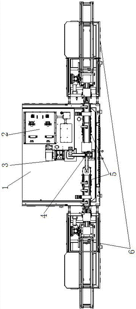
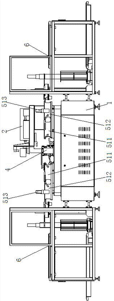
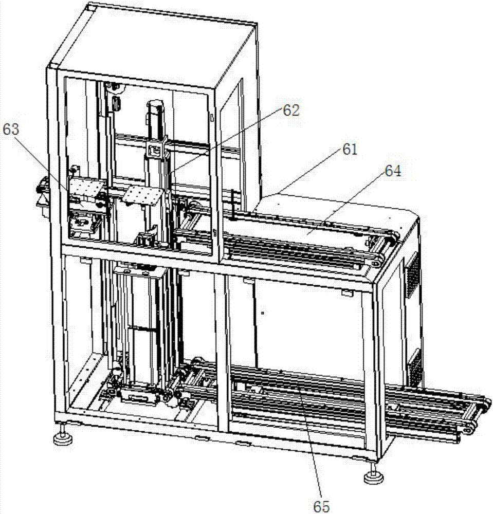
[0050] Embodiment one: if figure 1 and 2 As shown, the fully automatic solar cell laser processing equipment in this embodiment includes a workbench 1, a laser processing host 2, a cell processing table 3, a rotating mechanical arm assembly 4, a left and right cell buffer transfer assembly 5, and a left and right cell Connection assembly 6;

[0051] Both the above-mentioned laser processing host 2 and the cell processing table 3 are installed on the above-mentioned workbench 1, and the above-mentioned cell processing table 3 is located below the laser processing head of the above-mentioned laser processing host 2;

[0052] The above-mentioned rotating mechanical arm assembly 4 is installed on the workbench 1 on the side of the above-mentioned cell processing table 3, and can rotate horizontally on the above-mentioned workbench 1;

[0053] The above-mentioned left and right cell buffer transfer assembly 5 is installed on the workbench 1 on both sides of the above-mentioned ro...

Embodiment 2

[0067] Embodiment two: if Figures 14 to 16 As shown, in the first embodiment above, the cell processing table 3, the rotating mechanical arm assembly 4, the left and right cell buffer transfer assembly 5, and the left and right cell connection assembly 6 form a single-line processing system, and the above-mentioned laser processing host 2 is set There are 2 laser processing heads, which are treated with light splitting, so that the 2 laser processing heads independently emit laser light for processing. The above-mentioned single-line processing systems are provided with two, and are respectively installed on the workbench 1 on both sides of the laser processing host 2. The entire device forms a two-line processing system, and the corresponding two cell processing stations 3 are respectively installed under the two laser processing heads, that is, the entire device can independently form two processing production lines, and the two single-line processing systems Relatively ind...


PUM


Abstract

The invention relates to laser processing equipment for a full-automatic solar battery piece. The laser processing equipment comprises a workbench, a laser processing host, a battery piece processing table, a rotary mechanical arm assembly, left and right battery piece caching and transferring components and left and right battery piece connection assemblies, wherein the laser processing host and the battery piece processing table are both installed on the workbench; the battery piece processing table is arranged below a laser processing head of the laser processing host; the rotary mechanical arm assembly is installed on the workbench on one side of the battery piece processing table; the left and right battery piece caching and transferring components are installed on the workbench on the two sides of the rotary mechanical arm assembly; in the rotation process of the rotary mechanical arm assembly, the free end of the rotary mechanical arm assembly can rotate to the positions above the battery piece processing table and above the left and right battery piece caching and transferring components on the two sides of the rotary mechanical arm assembly respectively; and the left and right battery piece connection assemblies are installed on the two sides of the workbench. The laser processing equipment has the advantages of simple structure, convenience in use, high production efficiency and strong processing stability.

Description

technical field [0001] The invention relates to the technical field of cell laser processing, in particular to a fully automatic solar cell laser processing device. Background technique [0002] As photovoltaic solar energy, a new energy source, has attracted more and more attention and attention from governments and people of various countries, more and more high-efficiency production requirements have been put forward for related photovoltaic solar cell production equipment, and at the same time, how to improve the conversion efficiency of solar cells A lot of research has been invested, and the introduction of laser processing technology can not only improve the conversion efficiency of solar cells, but also reduce the overall cost of equipment and reduce environmental pollution. [0003] At present, the rapid development of new high-efficiency solar cells with back passivation technology, which represents the development direction of the industry, indicates that high-pre...

Claims


Application Information

Patent Timeline
Patent Type & Authority Patents(China)
IPC IPC(8): B23K26/362B23K26/70B25J11/00
CPCB25J11/005
Inventor 李志刚
Owner WUHAN DR LASER TECH CORP LTD
Learn More