Powder material compression molding method assisted by ultrasonic vibration

A powder material, press molding technology, applied in material molding presses, presses, manufacturing tools, etc., can solve the problems of uneven density distribution inside the compact, inconsistent effective pressure, pressure loss, etc., to achieve high quality Forming preparation, increasing effective pressure, increasing the effect of densification

Active Publication Date: 2017-08-29
INST OF CHEM MATERIAL CHINA ACADEMY OF ENG PHYSICS
View PDF9 Cites 0 Cited by
  • Summary
  • Abstract
  • Description
  • Claims
  • Application Information

AI Technical Summary

Problems solved by technology

[0002] Compression is an important process path in the field of mixed energetic powder material forming and charging, but this process faces important bottlenecks in innovative development, especially in terms of density and density uniformity, internal stress homogenization, and residual stress release.
Specifically, in the process of powder material compression molding, there is inevitably internal friction between the powder material particles and external friction between the particles and the mold wall (or soft mold), resulting in a gradual loss of pressure along the pressing direction, As a result, the effective pressure on the energetic powder material particles in different height layers and different radial positions is inconsistent, and the density distribution inside the green compact is not uniform.

Method used


Image

  • Powder material compression molding method assisted by ultrasonic vibration
  • Powder material compression molding method assisted by ultrasonic vibration
  • Powder material compression molding method assisted by ultrasonic vibration

Examples


Embodiment 1

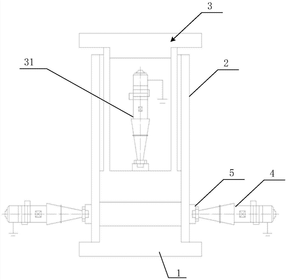
[0031] figure 1 It is a schematic structural diagram of the safety equipment for pressing and molding powder materials assisted by ultrasonic vibration provided in Embodiment 1 of the present invention. Such as figure 1 As shown, the equipment includes an ultrasonic base 1 , an ultrasonic die set 2 installed on the ultrasonic base 1 , an ultrasonic punch 3 used in conjunction with the ultrasonic die set 2 , and a hydraulic press for driving the ultrasonic punch 3 .

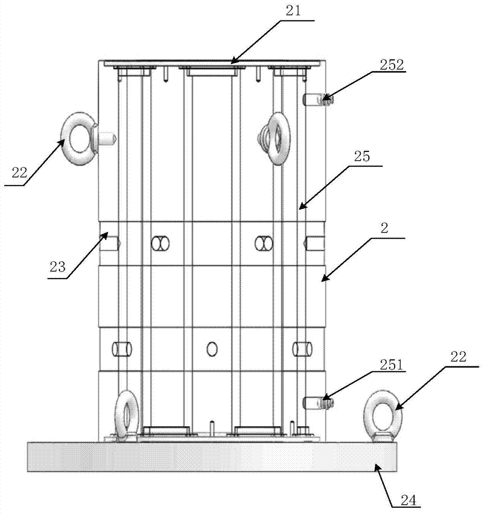
[0032] In this example, if figure 2 As shown, the ultrasonic die set 2 includes a cover plate 21 , eyebolts 22 , a powder pressing chamber 23 , a lower die 24 , and a circulating water cooling system. The circulating water cooling system includes a water pipe 25 , a liquid inlet 251 and a liquid outlet 252 . Eyebolts 22 are provided on the cover plate 21 and the lower die 24 . The joint between the powder pressing chamber 23 and the cover plate 21, the joint between the powder pressing chamber 23 and the liqui...

Embodiment 2

[0041] Embodiment 2 provides a powder material compression molding method assisted by ultrasonic vibration, which includes the following steps.

[0042] Step (1): Place the powder material to be pressed in the ultrasonic mold sleeve, between the ultrasonic punch and the ultrasonic base.

[0043] Step (2): Start the cooling water circulation system, the coolant is injected from the liquid inlet of the cooling water circulation system and flows out from the liquid outlet.

[0044] Step (2) Specifically, inject coolant into the liquid inlet of the ultrasonic mold sleeve and the liquid inlet of the ultrasonic punch, so that the coolant is injected from the liquid inlet of the cooling water circulation system and flows out from the liquid outlet, thereby starting the ultrasonic mold sleeve. The cooling water circulation system and the cooling water circulation system in the ultrasonic punch.

[0045] Step (3): Start the hydraulic press, and the ultrasonic punch makes relative moti...


PUM


Abstract

The invention relates to the technical field of pressing formation on powder materials, and provides a method for performing pressing formation on a powder material under assistance of ultrasonic vibration. The method comprises the following steps that safety equipment for performing the pressing formation on the powder material is established; a to-be-pressed powder material is put in an ultrasonic die sleeve; a hydraulic machine is started, an ultrasonic punch does a relative movement under action of the hydraulic machine, and the powder material is driven to do a downward movement so as to be pressed; and a finished product obtained after the powder material in the ultrasonic die sleeve is pressed is taken out. According to the technical solution provided by the invention, internal friction among particles of the powder material and external friction between the particles and a die wall of the ultrasonic die sleeve are reduced, effective pressure of grains on different layers is increased, internal density uniformity is improved, and internal stress is reduced, therefore high-quality formation preparation of the grains is realized.

Description

technical field [0001] The invention relates to the technical field of powder material compression molding, in particular to a powder material compression molding method assisted by ultrasonic vibration. Background technique [0002] Compression is an important process path in the field of mixed energetic powder material forming and charging, but this process faces important bottlenecks in the development of innovation, especially in terms of density and density uniformity, internal stress homogenization and residual stress release. Specifically, in the process of powder material compression molding, there is inevitably internal friction between the powder material particles and external friction between the particles and the mold wall (or soft mold), resulting in the pressure being gradually lost along the pressing direction, As a result, the effective pressure on the energetic powder material particles at different height layers and different radial positions is inconsiste...

Claims


Application Information

Patent Timeline
Patent Type & Authority Patents(China)
IPC IPC(8): B30B11/02B30B15/34
CPCB30B11/022B30B15/34
Inventor 吕珂臻韩超董向阳陈学平张锋雍炼冯立羊付诚刘鹏杨宝刚
Owner INST OF CHEM MATERIAL CHINA ACADEMY OF ENG PHYSICS
Why Eureka
Try Eureka