Method for preparing solid amorphous alloy thin strips with controllable microstructures

A technology of amorphous alloys and microstructures, which is used in instruments, material analysis by measuring secondary emissions, and material analysis, etc., can solve problems such as only being applicable, not knowing the main factors of the microstructure of solid-state amorphous alloys, and not understanding the effects, etc.

Active Publication Date: 2016-06-01
江苏非晶电气有限公司 +2
View PDF8 Cites 24 Cited by
  • Summary
  • Abstract
  • Description
  • Claims
  • Application Information

AI Technical Summary

Problems solved by technology

The main disadvantage of this method is that the three-dimensional image obtained by tilting the sample around a single tilt axis will be distorted along the direction parallel to the tilt axis.
The main disadvantage of this method is that this method is only suitable for samples with an original thickness greater than 50 microns
The main disadvantage of this method is: this method is only applicable to the deposition preparation method, and cannot be used for the high-speed planar flow continuous casting method.
The main reason for t...

Method used


Image

  • Method for preparing solid amorphous alloy thin strips with controllable microstructures
  • Method for preparing solid amorphous alloy thin strips with controllable microstructures
  • Method for preparing solid amorphous alloy thin strips with controllable microstructures

Examples


preparation example Construction

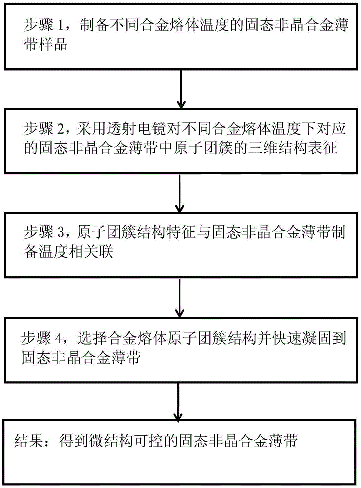
[0033] combine figure 1 , a method for preparing a solid amorphous alloy thin strip with controllable microstructure proposed by the present invention, comprising the following specific steps:

[0034] Step 1, preparing solid amorphous alloy thin strip samples at different alloy melt temperatures: the alloy melt is rapidly solidified into thin strips by high-speed planar flow continuous casting, and a series of alloy melts separated by a certain distance are prepared by changing the temperature of the alloy melt. Solid amorphous alloy thin strip sample at bulk temperature;

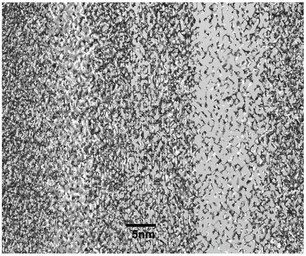
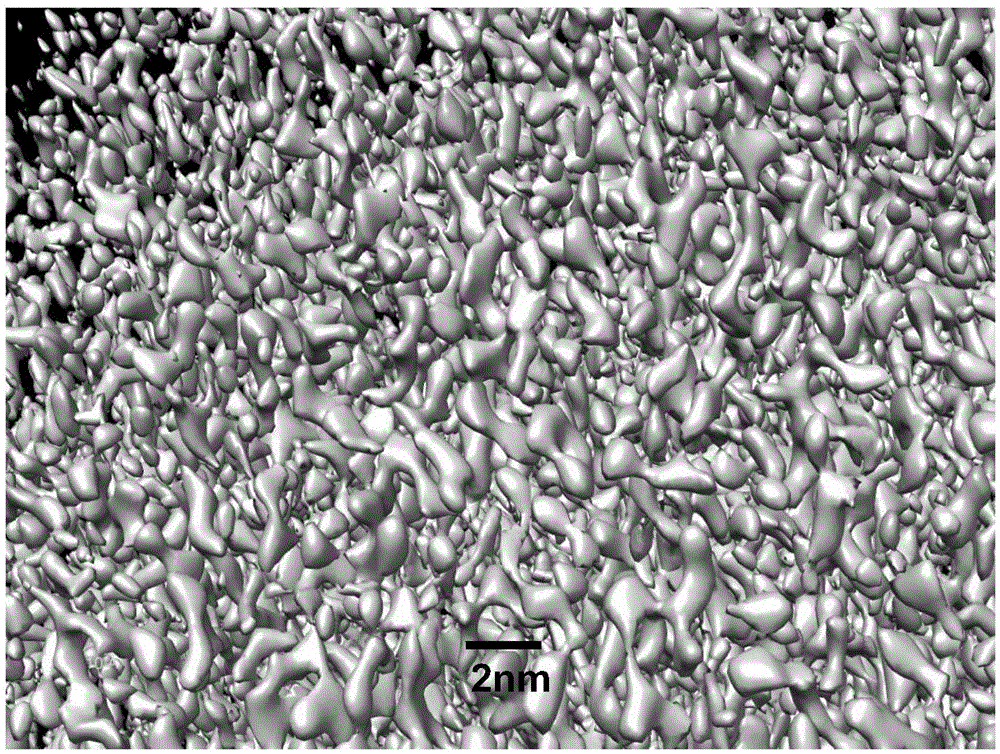
[0035] Step 2, use transmission electron microscopy to characterize the three-dimensional structure of atomic clusters in solid amorphous alloy ribbons corresponding to different alloy melt temperatures: install the solid amorphous alloy ribbon sample described in step 1 on a platform with tilting and rotating functions On the sample stage of the transmission electron microscope, in the case of a rotation...

Embodiment 1

[0039] Embodiment 1: adopt solid amorphous alloy Zr 48 Cu 45 Al 7 A thin strip (the subscript number in the chemical formula is at%), the solid amorphous alloy thin strip is prepared by the high-speed planar flow continuous casting method commonly used in this field.

[0040] The specific operation steps of using the microstructure-controllable solid-state amorphous alloy thin strip preparation method according to the present invention are as follows:

[0041] Step 1: including the following sub-steps in turn: (1) select the temperature of the alloy melt to be 1200° C., and use a high-speed planar flow continuous casting method to prepare a solid amorphous alloy thin strip with a thickness of 25 microns; (2) use an ultrasonic cutting machine (Gatan Inc. .Model: 601) Cut the six kinds of solid amorphous alloy thin strips into discs with a diameter of 3 mm; (3) place the discs in acetone for 10 minutes of ultrasonic treatment; (4) use a pit instrument (Gatan Inc.) to The cent...

Embodiment 2

[0047] Step 1: In order to obtain the microstructural characteristics of the solid amorphous alloy corresponding to the 1400°C alloy melt, first adjust the temperature of the alloy melt to 1400°C to prepare a solid amorphous alloy thin strip. The difference from Example 1 is that due to The temperature of the alloy melt increases by 200°C, which is about 17% higher than that of the alloy melt at 1200°C. Due to the increase of the temperature of the alloy melt, the cooling rate of the copper roll should be increased accordingly, so that the alloy melt at 1400 ° C can be rapidly solidified into a solid amorphous alloy strip within the same solidification time as the alloy melt at 1200 ° C, so To retain the atomic cluster structure of the 1400°C alloy melt in the solid amorphous alloy, the cooling rate needs to be increased by about 20%. In the process of preparing solid amorphous alloy thin strips with an alloy melt temperature of 1400°C, in order to improve the cooling capacity...


PUM


Abstract

The invention relates to a method for preparing solid amorphous alloy thin strips with controllable microstructures. The method is characterized by specifically comprising the steps that first, solid amorphous alloy thin strip samples at different alloy melt temperatures are prepared; second, the three-dimensional structures of atomic clusters in the solid amorphous alloy thin strips corresponding to different alloy melt temperatures are subjected to characterization by a transmission electron microscope; third, atomic cluster structure characteristics and the preparation temperatures of the solid amorphous alloy thin strips are related; fourth, the atomic cluster structures of alloy melt are selected and solidified to the solid amorphous alloy thin strips rapidly. According to the method, the microstructures of the solid amorphous alloy thin strips can be effectively controlled to achieve the designability and the controllability of the microstructures of the solid amorphous alloy thin strips and obviously improve the macroscopic physical performance of the solid amorphous alloy thin strips. The method for preparing the solid amorphous alloy thin strips with the controllable microstructures has the characteristics of being simple and convenient to implement, high in efficiency, low in cost, high in controllability and repeatability and high in technical reliability and the like, and is suitable for being widely applied in the technical field of preparation of metal functional materials.

Description

technical field [0001] The invention belongs to the technical field of preparation of metal functional materials, and in particular relates to a preparation method of a solid amorphous alloy strip with controllable microstructure. Background technique [0002] Metal alloys in a liquid state are not divided into anions and cations like water and other organic liquids, but form some very small atomic clusters. The size, geometry and characteristics of atomic clusters show obvious differences with the alloy composition and alloy melt temperature. The heating process of the alloy melt is the process of reducing the size of the atomic clusters, on the contrary, the cooling process of the alloy melt is the process of increasing the size of the atomic clusters. When the temperature rises, the atomic clusters with poor stability first decompose into smaller atomic clusters with better stability. The difference in the number of atoms may lead to changes in the geometry of the atomi...

Claims


Application Information

Patent Timeline
IPC IPC(8): C22C45/02C22C45/04C22C45/08C22C45/10C22C45/00G01N23/22
CPCG01N23/2202C22C45/00C22C45/001C22C45/003C22C45/005C22C45/008C22C45/02C22C45/04C22C45/08C22C45/10C22C1/11
Inventor 王岩国
Owner 江苏非晶电气有限公司
Why Eureka
Try Eureka