Combination type tunnel lining, culvert or underground comprehensive pipe gallery

A comprehensive pipe gallery and combined technology, applied in the field of steel pipes, can solve the problems that the support strength cannot be strictly guaranteed, affect the progress of the project, and invest in large equipment, so as to reduce the area of ​​the excavation section, save the amount of engineering, and increase the bearing capacity. increased effect

Inactive Publication Date: 2016-06-01
NANJING LIANZHONG CONSTR ENG TECH
View PDF15 Cites 5 Cited by
  • Summary
  • Abstract
  • Description
  • Claims
  • Application Information

AI Technical Summary

Problems solved by technology

The above-mentioned structure and construction method have the following problems: ① Generally speaking, the primary support layer (i.e. the primary lining layer) of the tunnel bears most of the load on the upper part of the cave, but the bearing capacity of the primary support layer depends not only on the inner steel arch The frame also depends on the cooperation and support of the concrete, and the concrete will not immediately play a load-bearing role when it is poured. It needs solidification and hardening time. During this period of time, the support strength cannot be strictly guaranteed, especially in the crust. Complicated areas, and then tunnel engineering collapse accidents will often occur
②. After solidification, the concrete is a purely rigid material, not easy to deform, not earthquake-resistant, easy to crack, easy to seep water after cracking, and difficult to repair. This is a common problem after the tunnel is in operation.
④. Concrete engineering needs solidification and hardening time, which affects the progress of the project
⑤. Special large-scale initial construction trolleys and corresponding molds are required, and the investment in equipment is large
⑥. Rebar binding is a labor-intensive construction with a large amount of labor and slow speed

Method used


Image

  • Combination type tunnel lining, culvert or underground comprehensive pipe gallery
  • Combination type tunnel lining, culvert or underground comprehensive pipe gallery
  • Combination type tunnel lining, culvert or underground comprehensive pipe gallery

Examples


Embodiment Construction

[0026] The technical solution of the present invention will be further described below in conjunction with the accompanying drawings.

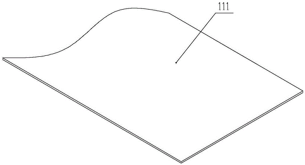
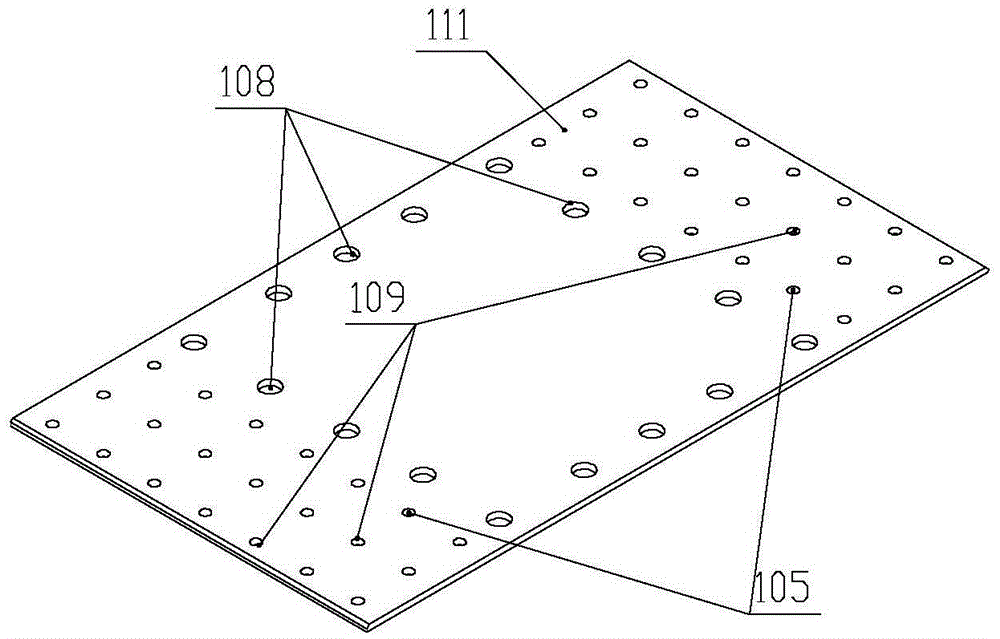
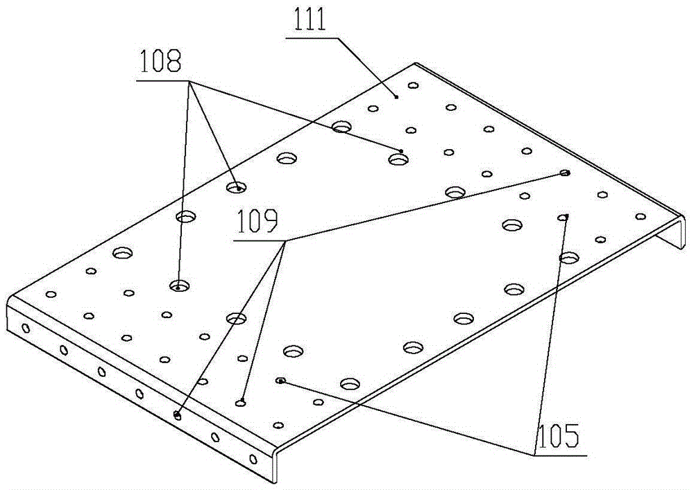
[0027] The invention discloses a combined tunnel lining, culvert or underground comprehensive pipe gallery, which includes a pipeline 100 assembled from curved unit plates 101 along the circumferential and axial directions; wherein, when the unit plates 101 are spliced ​​along the axial direction, The contact end of adjacent unit plates 101 has a hollow cavity structure 104, the cross-sectional periphery of the hollow cavity structure 104 is closed, and the contact surface of the adjacent hollow cavity structure 104 is a splicing connection surface, such as Figure 9 , 10 , 11, 12 shown. Preferably, a connection hole 105 may be opened on the contact surface, and connected by workpieces such as bolts. Since the hollow cavity structure is located outside the tunnel, culvert or underground comprehensive pipe gallery, a splicing operation hole 1...


PUM


Abstract

The invention discloses a combination type tunnel lining, a culvert or an underground comprehensive pipe gallery. The combination type tunnel lining, the culvert or the underground comprehensive pipe gallery comprises a pipeline formed by axially assembling unit plate pieces with radians in the circumferential direction. Each unit plate piece is provided with a pair of arc-shaped sides and a pair of straight sides. The arc-shaped sides are outwards folded to form cavity structures of which the periphery of each cross section is closed. The combination type tunnel lining, the culvert or the underground comprehensive pipe gallery has the advantages that the cavity structures of the comprehensive pipe gallery are formed by bending the cavity structures to form cavity pipe columns with the closed cross sections, auxiliary steel plates or blocking steel plates do not need to be additionally arranged, welding seams are reduced, and the strength of the cavity structures for forming arched beams is high; connecting pieces among the adjacent unit plate pieces of the comprehensive pipe gallery are all hidden inside structural pieces and do not need to be exposed inside a tunnel or the culvert, and the utilization rate of the internal space of the tunnel or the culvert is increased; in addition, operation holes are formed in the inner side of the pipe gallery, and splicing work can be easily competed by construction personnel only on the inner side of the pipe gallery.

Description

technical field [0001] The invention discloses a steel pipe, in particular to a combined tunnel lining, culvert or underground comprehensive pipe gallery. Background technique [0002] Tunnel lining is a permanent support structure built with steel arch frames and steel-concrete materials along the upper circumferential arch wall of the tunnel body to prevent the surrounding rock in the tunnel from deformation or collapse. The existing tunnel lining is generally provided with a primary support layer and a secondary lining layer. The primary support layer structure is composed of I-beams, arch frames, steel mesh, anchor rods and shotcrete, which are used to withstand the pressure generated by the plastic deformation of the structure above the cavern after tunnel excavation and prevent the surrounding rock from deforming or collapsing. After setting up the primary support layer, the tunnel needs to carry out secondary lining. The secondary lining is built with waterproof clot...

Claims


Application Information

Patent Timeline
Patent Type & Authority Applications(China)
IPC IPC(8): E21D11/10E02D29/045E21D9/00
CPCE21D11/10E02D29/045E21D9/00
Inventor 战福军
Owner NANJING LIANZHONG CONSTR ENG TECH
Why Eureka
Try Eureka