
Treatment device for pitch smoke

A technology for asphalt flue gas and treatment equipment, which is applied in the direction of combustion methods, combustion types, incinerators, etc., can solve problems affecting road traffic safety, low efficiency, waste of resources, etc., and achieve simple and reasonable structure, avoid excessive dust, and protect the environment The effect of little pollution

Inactive Publication Date: 2016-06-01
郑焕刚
View PDF0 Cites 6 Cited by
  • Summary
  • Abstract
  • Description
  • Claims
  • Application Information

AI Technical Summary

Problems solved by technology

[0002] Traditional road maintenance technology can no longer meet the requirements of the country and society because of the waste of resources, environmental pollution, and low efficiency. The hot-in-place regeneration road maintenance technology is gradually becoming the industry's development trend because it can realize 100% recycling of old asphalt pavement materials. Mainstream, has been promoted and used in more and more regions
In the process of in-situ heat regeneration of asphalt pavement, the heating system is used to heat the asphalt pavement or asphalt mixture when it involves continuous actions such as heating the pavement, milling, mixing and paving. When the asphalt is heated to a certain temperature, it will produce yellow Asphalt flue gas, asphalt flue gas mainly contains low-carbon chain hydrocarbons, and a small amount of nitrogen, sulfur heterocyclic compounds and polycyclic aromatic hydrocarbons. These substances cause environmental pollution and seriously affect the growth and development of humans, animals, and plants. If people stay in the environment polluted by asphalt oil fume for a long time, it can cause diseases such as respiratory tract and skin, and induce cancer at the same time.

Method used


Image

  • Treatment device for pitch smoke

Examples


Embodiment Construction

[0011] The following will clearly and completely describe the technical solutions in the embodiments of the present invention with reference to the accompanying drawings in the embodiments of the present invention. Obviously, the described embodiments are only some, not all, embodiments of the present invention. Based on the embodiments of the present invention, all other embodiments obtained by persons of ordinary skill in the art without making creative efforts belong to the protection scope of the present invention.

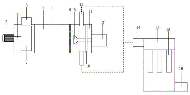
[0012] see figure 1 , in an embodiment of the present invention, an asphalt flue gas treatment device includes a treatment box 1, the left and right ends of the treatment box 1 are respectively provided with a motor 2 and a burner 3, and the output end of the motor 2 is connected to the rotating shaft 4 through transmission. , the rotating shaft 4 moves through the left side wall of the processing box 1 through bearings, and the rotating shaft 4 is fixedly con...


PUM


Abstract

The invention discloses a treatment device for pitch smoke. The treatment device comprises a treatment box body, a motor and a combustor are arranged at the left end and the right end of the treatment box body respectively, the output end of the motor is connected to a rotating shaft in a transmission mode, the rotating shaft movably penetrates through the left side wall of the treatment box body through a bearing and is fixedly connected to a fan in the treatment box body, a pitch smoke recovery pipe matched with an air inlet of the fan is arranged at the upper end of the treatment box body, and an air outlet of the fan is arranged horizontally and towards the right; a combustion chamber is formed in the treatment box body, a combustion head of the combustor extends into the combustion chamber, and a radiation net is arranged on the left side of the combustion head and is arranged in the combustion chamber. The treatment device is simple and reasonable in structure and convenient to use, and integrally the pitch smoke can be treated effectively and quickly so that the pollution of the pitch smoke to the environment can be lowered to the minimum level; a dust treatment device is arranged so that the condition of excessive dust at the later stage can be avoided.

Description

technical field [0001] The invention relates to a waste gas treatment device, in particular to an asphalt flue gas treatment device. Background technique [0002] Traditional road maintenance technology can no longer meet the requirements of the country and society because of the waste of resources, environmental pollution, and low efficiency. The hot-in-place regeneration road maintenance technology is gradually becoming the industry's development trend because it can realize 100% recycling of old asphalt pavement materials. The mainstream has been promoted and used in more and more regions. In the process of in-situ heat regeneration of asphalt pavement, the heating system is used to heat the asphalt pavement or asphalt mixture when it involves continuous actions such as heating the pavement, milling, mixing and paving. When the asphalt is heated to a certain temperature, it will produce yellow Asphalt flue gas, asphalt flue gas mainly contains low-carbon chain hydrocarbo...

Claims


Application Information

Patent Timeline
Patent Type & Authority Applications(China)
IPC IPC(8): F23G7/06
CPCF23G7/061F23G2209/14
Inventor 郑焕刚
Owner 郑焕刚
Learn More