Hall encoder
A Hall encoder and housing technology, applied in the field of Hall encoders, can solve the problems of Hall encoder application limitations, high production costs, and low resolution, and achieve simple structure, easy processing and production, and high resolution. Effect
- Summary
- Abstract
- Description
- Claims
- Application Information
AI Technical Summary
Problems solved by technology
Method used
Image

Examples
Embodiment Construction
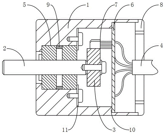
[0023] The invention provides a Hall encoder, such as figure 1 As shown, it includes a casing 1, a rotating shaft 2, a multi-stage magnetized magnet 3 and a signal output line 4, wherein the inner wall of the casing 1 is fixed with a bearing group 5 and a circuit board 6, and the bearing group is embedded in the casing In the cavity, the accommodation space for the multi-stage magnetized magnet 3 is formed between the bearing group 5 and the circuit board 6, and the rotating shaft 2 is connected to the bearing group 5. The bearing group includes two bearings, and a bushing 9 is arranged between the two bearings. , to ensure the coaxiality and reliability of the rotating shaft during the rotation process, and one end is located outside the casing 1, and the other end is fixedly connected to the multi-stage magnetized magnet 3 in the accommodation space, refined, multi-stage magnetized The magnet 3 is fixedly connected to the rotating shaft 2 by a bolt, and the axis center of th...
PUM
 Abstract
Description
Claims
Application Information
 - Generate Ideas
- Intellectual Property
- Life Sciences
- Materials
- Tech Scout
- Unparalleled Data Quality
- Higher Quality Content
- 60% Fewer Hallucinations
Browse by: Latest US Patents, China's latest patents, Technical Efficacy Thesaurus, Application Domain, Technology Topic, Popular Technical Reports.
© 2025 PatSnap. All rights reserved.Legal|Privacy policy|Modern Slavery Act Transparency Statement|Sitemap|About US| Contact US: help@patsnap.com