Wheel hub one-piece electric device and driving and braking method thereof
A technology of electric devices and hubs, applied in the direction of electromechanical devices, power devices, electric vehicles, etc., can solve the problems of limitations, low weight/volume ratio, low power, and few types, and achieve the effect of low cost and simple structure
- Summary
- Abstract
- Description
- Claims
- Application Information
AI Technical Summary
Problems solved by technology
Method used
Image

Examples
Embodiment 1
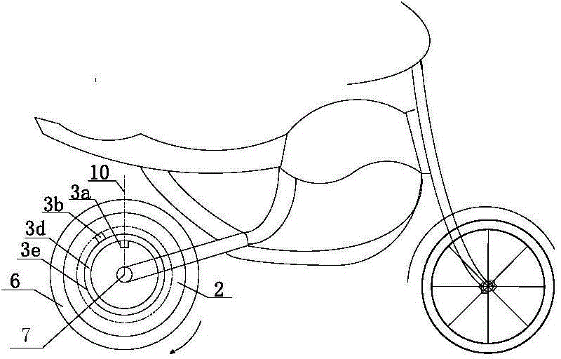
[0094] A wheel hub electric device of an electric two-wheeled vehicle with a front and rear wheel structure. Figure 1a In the frame 4 shown, the circumference of the wheel 5 is 1000 mm, the battery pack 8 is a lithium iron phosphate battery, and the battery pack 8 is installed inside the frame 4; the wheel hub conjoined electric device is arranged on the rear wheel of the car. The coaxial rotating body 3e of the electric device 3 is an annular titanium-aluminum alloy ring with a rotating shaft and a circumference of 300mm. The outer edge of the alloy ring is fixedly connected to a rotor unit 3b, and the mechanical device is fixedly connected to the fixed shaft inside the alloy ring On the upper side, a stator unit 3a is installed; the coaxial rotating body 3e is installed coaxially with the hub 6, and a reduction / torque conversion device 2 composed of several gears is arranged in between, and the reduction / torque conversion device 2 realizes the connection with the hub 6 Mechani...
Embodiment 2
[0101] Change the timing current of the power supply modulator in Example 1 to: T 1 The power-on time domain is set to a constant current corresponding to two periods of time and intensity, and the characteristic is the current intensity I of the last 1 / 2 time 2 / A is the current intensity I in the first 1 / 2 time 1 / A half; the working logic of the power modulator is adjusted at the same time as: when the stator unit winding starts to be energized, the power modulator will change to I within 5s 1 Strength 16A (corresponding to I 2 It is 8A) as the reference, corresponding to the current sequence of the wheel rotation cycle to automatically increase the output intensity by 10% every next cycle, the relative ratio of the two power-on time domains is the set 2:1; wait for driving control from the 6th second The next work instruction of the device 9: if there is no input instruction from the drive control device 9a, the power modulator 1 sleeps; if the instruction given by the drive c...
Embodiment 3
[0104] Optimize the power-on procedure of the power modulator on the basis of embodiment 2: change T 1 The energization time domain is set to 5 segments of current with the same energization time but the current intensity decreasing regularly, and the 5 segments of energization intensity is K*I 1 The linear relationship of / A decreases gradually, and the decrease coefficient K is 0.7, which is T 1 The current intensities of the 5 energizing periods in the sequence are 20.0A, 14.0A, 9.8A, 6.9A, 4.8A, respectively. The design of power-on program logic using conventional electronic circuits to achieve control is more complicated, and the manufacturing cost is also higher. The power modulator is changed to a mature pulse digital technology. .
[0105] The core module of the power modulator includes a conventional CPU and a drive module with a design power of 500W. Its detailed working logic is as Figure 5b As shown, the pulse conversion conditioning circuit mainly completes the conve...
PUM
 Abstract
Description
Claims
Application Information
 - R&D
- Intellectual Property
- Life Sciences
- Materials
- Tech Scout
- Unparalleled Data Quality
- Higher Quality Content
- 60% Fewer Hallucinations
Browse by: Latest US Patents, China's latest patents, Technical Efficacy Thesaurus, Application Domain, Technology Topic, Popular Technical Reports.
© 2025 PatSnap. All rights reserved.Legal|Privacy policy|Modern Slavery Act Transparency Statement|Sitemap|About US| Contact US: help@patsnap.com