Mechanical arm used for replacing spiral liner plate

A manipulator and screw technology, applied in the field of manipulators, can solve the problems of inability to fit the screw lining, inconvenient on-site installation, large volume and weight, etc., and achieve the effects of easy adjustment, simple and compact structure, and large driving torque.

Active Publication Date: 2016-06-08
CITIC HEAVY INDUSTRIES CO LTD +1
View PDF8 Cites 4 Cited by
  • Summary
  • Abstract
  • Description
  • Claims
  • Application Information

AI Technical Summary

Problems solved by technology

[0004] At present, the relining manipulator equipment in the world is only suitable for ball mills, and there is no mechanized equipment for replacing the spiral liner of vertical stirring mills, because the liner of ball mills has a regular shape, and the manipulator is easy to locate and close. The shape of the liner of the type stirring mill is a spiral surface, and the existing manipulator cannot fit the spiral liner, and cannot complete the positioning and disassembly of the spiral liner
[0005] Usually, the lining plate of a large vertical mixing mill weighs about 2 to 3 tons, has a complex shape (spiral surface structure), large volume and weight, and is extremely inconvenient to install on site.
Therefore, the vertical mixing mill is to manually replace the liner, and the workers put the liner into the grinding body through the workshop vehicle, manual hoist, hinge, crowbar, etc., which is time-consuming, labor-intensive, and poor in safety.

Method used


Image

  • Mechanical arm used for replacing spiral liner plate
  • Mechanical arm used for replacing spiral liner plate
  • Mechanical arm used for replacing spiral liner plate

Examples


Embodiment Construction

[0030] The present invention will be further described through specific embodiments below in conjunction with the accompanying drawings.

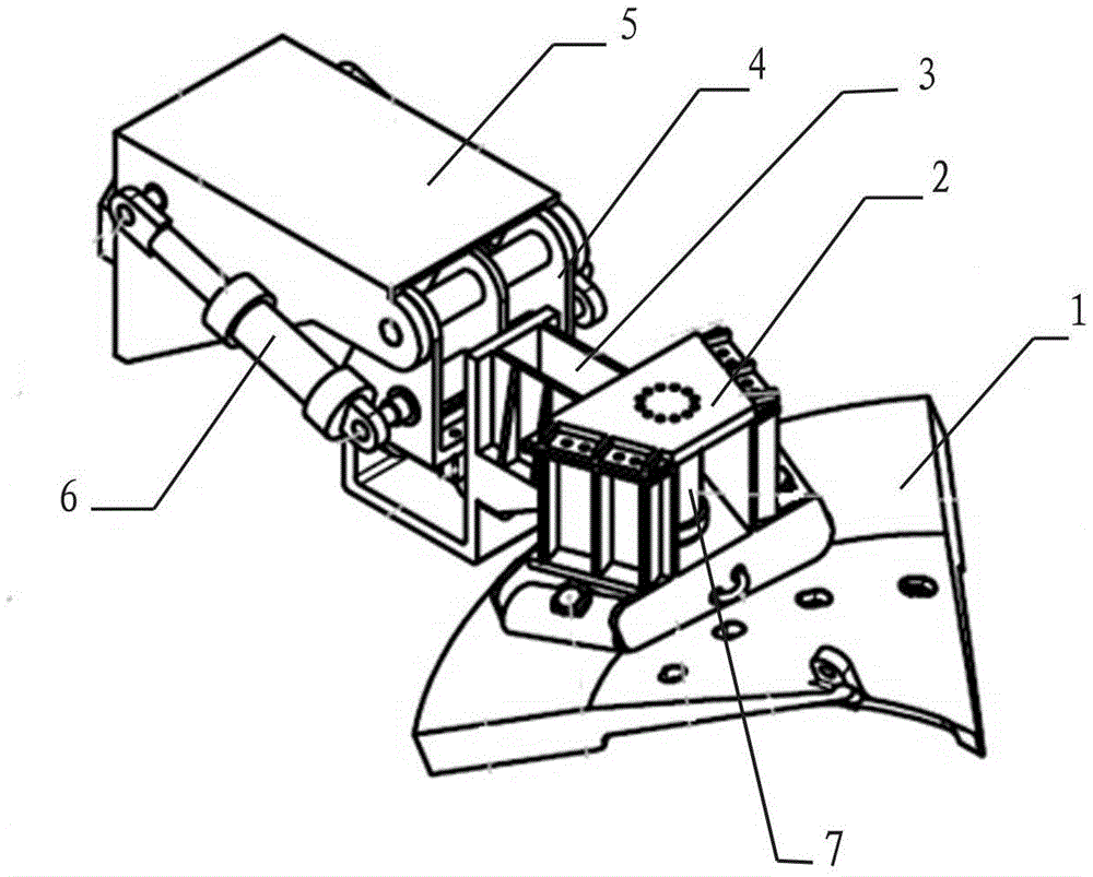
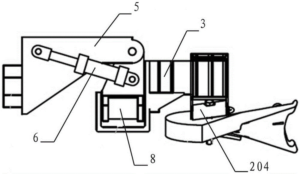
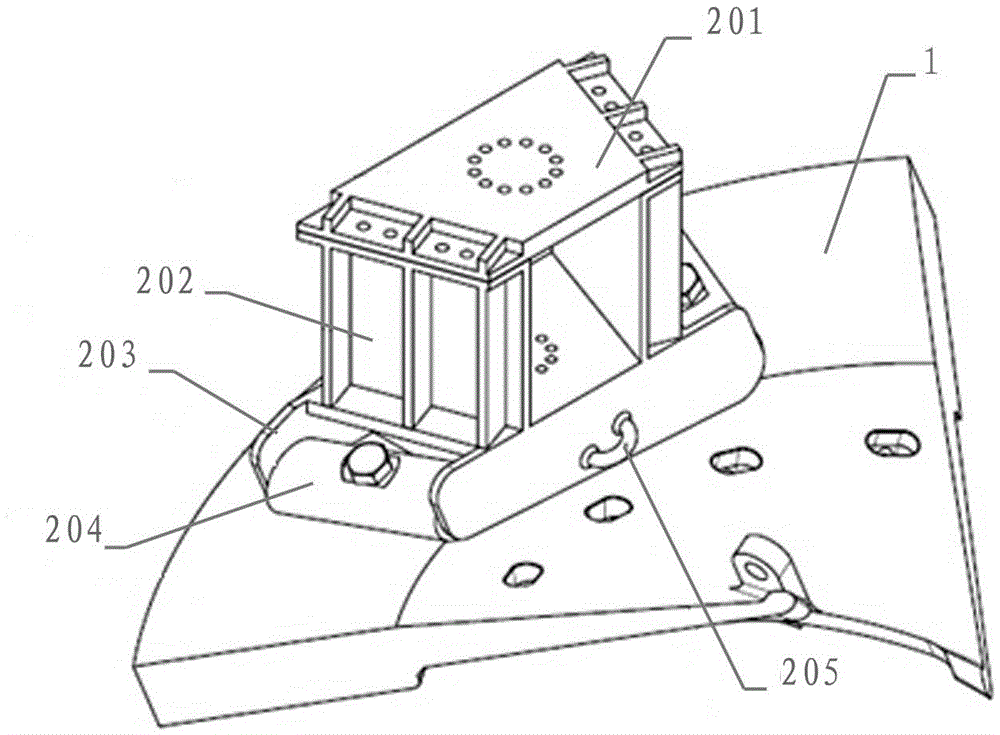
[0031] As shown in the figure, a manipulator for replacing the spiral liner is installed at the end of the mechanical arm of the liner replacement robot, including the connecting tool 2, the pitch joint, the joint for fitting the spiral surface and the positioning joint for the installation hole, to be replaced After the spiral liner 1 is put on the connecting tool 2, through the gradual adjustment and cooperation of each joint, the adjustment and positioning of the spiral liner 1 posture are realized, so that the spiral liner 1 can be connected with the spiral support plate of the vertical mixing mill Fit, and the installation hole of the spiral lining 1 is aligned with the installation hole of the spiral supporting plate, so as to realize the installation of the spiral lining 1.

[0032] In the above composition structure, the connecting ...


PUM


Abstract

The invention discloses a mechanical arm used for replacing a spiral liner plate. The mechanical arm comprises a linking tool, a pitching joint, a spiral curved surface attaching joint and an installation hole positioning joint. The spiral liner plate to be replaced is fixed to the linking tool. The pitching joint comprises a pitching connecting plate and a support, and the pitching action of the pitching joint is controlled by a drive mechanism arranged between the pitching connecting plate and the support. The spiral curved surface attaching joint comprises a tool connecting mechanism and a rotating mechanism I. The linking tool is connected to the tool connecting mechanism. The rotating mechanism I drives the linking tool to rotate. The installation hole positioning joint is composed of a rotating mechanism II arranged on the linking tool. The linking tool is driven to rotate in the horizontal plane. Pitching rotation, rotation in the horizontal plane and rotation in the vertical plane of the mechanical arm are completed through the coordination of the three joints, the posture of the spiral liner plate is adjusted gradually so that the spiral liner plate can be well attached to a spiral supporting plate of a vertical stirring mill and an installation hole can be positioned, and the mechanization and automation degree of replacing the spiral liner plate is greatly improved.

Description

technical field [0001] The invention belongs to the technical field of vertical stirring mills, and in particular relates to a manipulator for replacing a spiral liner. Background technique [0002] In the field of mining equipment, the liner of the mill is a consumable and needs to be replaced regularly. With the development of mining equipment technology, the weight and size of the liner of the mill are getting larger and larger. The weight of a liner is generally more than 1 ton , or even 3-4 tons, manual disassembly and replacement will significantly increase the downtime and maintenance time of the equipment, and there is a great potential safety hazard. [0003] The load of traditional industrial robots is generally around tens of kilograms, requiring fast speed and precise positioning. Since the load is not large, most of them are driven by motors. Technically, the greater the load, the more difficult it is to ensure the positioning accuracy, strength, and rigidity o...

Claims


Application Information

Patent Timeline
Patent Type & Authority Applications(China)
IPC IPC(8): B25J17/00B25B11/00B25J5/00B23P19/04
CPCB23P19/04B25B11/00B25J5/00B25J17/00
Inventor 夏莹张路明田振华宋怀辉马连铭王滨蒋祺鹏
Owner CITIC HEAVY INDUSTRIES CO LTD
Why Eureka
Try Eureka