Automatic ignition control system and method for stove burning of hot blast stove

An automatic ignition and control system technology, applied in the direction of furnaces, blast furnaces, heating furnaces, etc., can solve the problems of structural damage to the combustion chamber of hot blast stoves, increase the labor intensity of operators, and heat loss of hot blast stoves, and achieve stable automatic ignition control, The effect of reducing labor intensity and eliminating deflagration

Active Publication Date: 2016-06-08
WISDRI ENG & RES INC LTD
View PDF4 Cites 3 Cited by
  • Summary
  • Abstract
  • Description
  • Claims
  • Application Information

AI Technical Summary

Problems solved by technology

[0003] The combination of gas flow and air flow in the ignition process determines whether the ignition process is safe. If the gas is first followed by the air, deflagration will easily occur and cause damage to the combustion chamber structure of the hot blast stove; if the amount of advance and excess air is too much, It will also cause excessive heat loss in the hot blast furnace
Therefore, realizing the safe, energy-saving and stable ignition of the hot blast stove is a problem in realizing the automatic control of the hot blast stove. At present, most blast furnace hot blast stoves are ignited by manual direct control of the valve positions of the gas and air regulating valves for ignition. After the ignition is completed, Switching to automatic or semi-automatic control of gas flow and air flow will increase the labor intensity of operators, and may cause deflagration due to problems such as regulating valves, lines, and combustion-supporting fans.

Method used


Image

  • Automatic ignition control system and method for stove burning of hot blast stove
  • Automatic ignition control system and method for stove burning of hot blast stove
  • Automatic ignition control system and method for stove burning of hot blast stove

Examples


Embodiment Construction

[0028] The present invention will be further described below in conjunction with the embodiments and accompanying drawings.

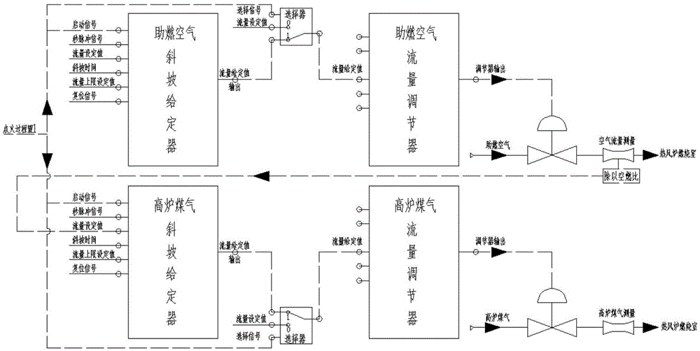
[0029] refer to figure 1 As shown, the automatic ignition control system of the hot blast stove according to the present invention includes an air ramp setter, an air flow signal selector, an air flow regulator, a gas ramp setter, a gas flow signal selector, and a gas flow regulator The air ramp setter and the gas ramp setter both include 6 input ports and 1 output port (each port of the air ramp setter and the gas ramp setter is realized by programming the PLC controller), 6 The input ports are: start signal (Boolean quantity) input terminal, second pulse signal input terminal, flow setting value input terminal, ramp time input terminal, flow upper limit setting value input terminal, reset signal input terminal (Boolean quantity), 1 output port is the flow given value output port;

[0030] The start signal input terminal and flow given value output t...


PUM


Abstract

The invention discloses an automatic ignition control system and method for stove burning of a hot blast stove. The system at least comprises an air slope setter, an air flow signal selector, an air flow adjuster, a coal gas slope setter, a coal gas flow signal selector and a coal gas flow adjuster. According to the method, after a combustion signal is received, an air flow set value output to the air flow adjuster by the air slope setter is gradually increased, and a combustion-supporting air adjusting valve is controlled to gradually increase an air flow; the coal gas flow set value on an input port of the coal gas slope setter follows the air flow actual-measurement value to be gradually increased, and is output to the coal gas flow adjuster, and a coal gas adjuster is controlled to increase the coal gas amount, so that ignition is achieved; an ignition task is completed until the air flow actual-measurement value is equal to the set value of the air slope setter, and the coal gas flow actual-measurement value is equal to the set value of the coal gas slope setter; and finally, the normal stove burning process is executed through the air flow adjuster and the coal gas flow adjuster. According to the system and method, flow stable control can be effectively achieved, the coal gas flow follows the air flow actual-measurement value to achieve proportional control, and automatic and safe ignition is achieved.

Description

technical field [0001] The invention is applied in the technical field of automatic control of blast furnace ironmaking, and in particular relates to an automatic ignition control system and method for a hot blast stove. Background technique [0002] The hot blast stove occupies an important position in the blast furnace ironmaking process. It heats the checker brick regenerator in the furnace by burning gas, and then heats the cold air passing through the hot blast stove regenerator to about 1200°C and sends it to the blast furnace to produce blast furnace coke. and coal injection to provide combustion temperature and oxygen; generally, a blast furnace is equipped with 3 or 4 hot blast stoves, and adopts 2 firing and 1 delivery, 3 burning and 1 delivery, 2 burning and 2 delivery, cross-parallel connection and other furnace replacement systems, each hot blast stove Because the working process is different, it is divided into three states: air supply, simmering furnace, and c...

Claims


Application Information

Patent Timeline
Patent Type & Authority Applications(China)
IPC IPC(8): C21B9/00
CPCC21B9/00
Inventor 李清忠叶理德刘江波
Owner WISDRI ENG & RES INC LTD
Why Eureka
Try Eureka