Thermo-acoustic engine device

A thermoacoustic engine, sound power technology, applied in the direction of machines/engines, mechanisms that generate mechanical power, mechanical equipment, etc., can solve the problems of sound power transmission and the inability of output power to be directly utilized.

Active Publication Date: 2016-06-08
TONGJI UNIV
View PDF5 Cites 11 Cited by
  • Summary
  • Abstract
  • Description
  • Claims
  • Application Information

AI Technical Summary

Problems solved by technology

However, since the cold-end heat exchanger and resonance tube of the thermoacoustic system are in a low-temperature environment, their output power can

Method used


Image

  • Thermo-acoustic engine device
  • Thermo-acoustic engine device
  • Thermo-acoustic engine device

Examples


Embodiment 1

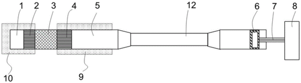
[0031] A standing wave thermoacoustic engine device, its structure is as follows figure 1 As shown, it includes a thermoacoustic engine assembly and a generator 8. The thermoacoustic engine assembly includes a hot-end gas storage 1, a hot-end heat exchanger 2, a regenerator 3, a cold-end heat exchanger 4, and a resonance tube 5 connected in sequence. The resonance tube 5 is also sequentially connected to the acoustic output assembly 12 and the generator assembly, the acoustic output assembly 12 is a vessel, the generator assembly includes a piston 6, a connecting rod 7 and a generator 8 connected in sequence, and the piston 6 is also connected to the vessel, Both the cold-end heat exchanger 4 and the resonance tube 5 are placed in the low-temperature cold source 9 , and the hot-end gas storage 1 and the hot-end heat exchanger 2 are both placed in the high-temperature heat source 10 .

[0032] The sound work generated by the thermoacoustic engine device is transmitted from the ...

Embodiment 2

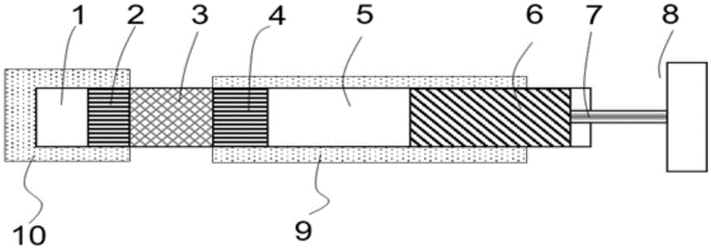
[0035] A standing wave thermoacoustic engine device, its structure is as follows figure 2 As shown, compared with Embodiment 1, most of the structures are the same, except that the sound power output assembly 12 in this embodiment is the piston 6 of the generator assembly, but compared with Embodiment 1, the length of the piston 6 is longer. The top of the piston 6 in this embodiment extends into the low-temperature environment, and the bottom is connected with the sound power utilization assembly 8. The temperature gradient from temperature to room temperature enables the generator 8 to work normally. Piston 6 is preferably made of materials with low thermal conductivity, such as bakelite, fiberglass, etc., and can also be made of stainless steel.

Embodiment 3

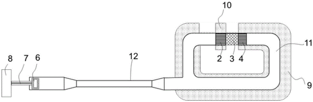
[0037] A traveling wave thermoacoustic engine device, its structure is as follows image 3 As shown, it includes a thermoacoustic engine assembly and a generator assembly. The thermoacoustic engine assembly includes a hot-end heat exchanger 2, a regenerator 3, a cold-end heat exchanger 4, and a feedback pipe 11 connected in sequence. The feedback pipe 11 is also connected in sequence The sound power output assembly 12 and the generator assembly, the sound power output assembly 12 is a pulse tube, the generator assembly includes a piston 6, a connecting rod 7 and a generator 8 connected in sequence, the piston 6 is also connected to the pulse tube, and the cold end heat exchanger 4 , Feedback pipe 11 are all placed in the low-temperature cold source 9, and the hot-end gas storage 1 and the hot-end heat exchanger 2 are all placed in the high-temperature heat source 10.


PUM


Abstract

The invention relates to a thermo-acoustic engine device which comprises a thermo-acoustic engine component, an acoustic power utilization component and an acoustic power outputting component, wherein the thermo-acoustic engine component works in the low-temperature environment; the acoustic power utilization component works in the room temperature environment; the two ends of the acoustic power outputting component are connected with the thermo-acoustic engine component and the acoustic power utilization component respectively. Compared with the prior art, the thermo-acoustic engine device has the advantages of small acoustic power loss, high efficiency, simple device structure, stability in running and the like.

Description

technical field [0001] The invention relates to a thermoacoustic engine device, in particular to a thermoacoustic engine device utilizing the cold energy of liquefied natural gas. Background technique [0002] A thermoacoustic engine is a device that converts heat energy into sound work through the thermoacoustic effect. The advantages of a thermoacoustic engine are the absence of moving parts, low cost and ease of manufacture. However, the application of thermoacoustic engines is limited by their large size and low thermoacoustic conversion efficiency. In 1999, Backhaus and Swift of the Los Alamos National Laboratory in the United States published an article in Nature, introducing a thermoacoustic Stirling engine developed by them. Its thermal efficiency is as high as 0.3, which is completely comparable to the traditional internal combustion engine (0.25 —0.4) and piston Stirling engines (0.20-0.38). This has aroused the great attention of scientific researchers and indu...

Claims


Application Information

Patent Timeline
IPC IPC(8): F03G7/00
CPCF03G7/00
Inventor 林玉哲朱绍伟
Owner TONGJI UNIV
Why Eureka
Try Eureka