Broad-band high-gain scannable panel antenna of parabolic reflection surface feeding

A flat-panel antenna and reflective surface technology, which is applied in the direction of antenna, antenna grounding switch structure connection, electrical components, etc., can solve the problems of excessive volume and complexity, and achieve the effect of large volume, slow dynamic response and difficult control

Inactive Publication Date: 2016-06-08
SHANGHAI UNIV
View PDF2 Cites 31 Cited by
  • Summary
  • Abstract
  • Description
  • Claims
  • Application Information

AI Technical Summary

Problems solved by technology

The feeding structure of the traditional parabolic antenna is a phased array str...

Method used


Image

  • Broad-band high-gain scannable panel antenna of parabolic reflection surface feeding
  • Broad-band high-gain scannable panel antenna of parabolic reflection surface feeding
  • Broad-band high-gain scannable panel antenna of parabolic reflection surface feeding

Examples


Embodiment 1

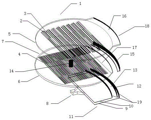
[0044] 1. see Figure 1 to Figure 11 , the broadband high-gain scannable panel antenna fed by the parabolic reflector, including the radiation unit and the feed network, is characterized in that: the structure is divided into upper, middle and lower three-layer structure:

[0045] 1) The superstructure includes:

[0046] ①Series feed structure (1): It is composed of upper and lower disc-shaped metal plates (5, 6). The upper disc-shaped metal plate (5) has impedance matching grooves (3) arranged in parallel, and the lower disc There are rectangular comb-tooth-shaped convex strips (4) arranged in parallel on the metal plate (6), and the center of circle between the upper and lower disc-shaped metal plates (5, 6) is connected by a rotary joint (14) so ​​that the upper and lower The two disc-shaped metal plates (5, 6) can rotate relative to each other; the air layer (7) is filled between the upper and lower disc-shaped metal plates (5, 6);

[0047] ② There is a VICTS radiating u...

Embodiment 2

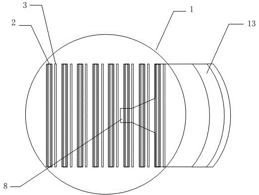
[0052] see Figure 1 to Figure 11 , this embodiment is basically the same as Embodiment 1, and the special features are as follows. The antenna is divided into upper, middle and lower layers. The upper series feed network and the VICTS radiating unit such as Image 6 , 7 , 8, the height of the series feed network (1) and the width of the step-type variable-tilt tangential branch slot (2) determine the operating frequency of the antenna. Adjust the height and width of the impedance matching slot (3), and the step The width of each step of the tangential branch slot with variable inclination angle can widen the working bandwidth of the antenna. The series feed network (1) adopts a height-gradient structure to ensure that each step-type variable inclination tangentially radiates the same energy to the branch slots (2), and also ensures that most of the energy is radiated from the radiation unit.

[0053] The rectangular comb tooth slow wave structure (4) adopts a structure wi...

Embodiment 3

[0056] see Figure 1 to Figure 11 , this embodiment is basically the same as Embodiment 1, and the special features are as follows. The upper series feed network and the VICTS radiating unit such as Image 6 , 7 , 8 shown. Figure 7 The black part in the middle is metal, and the white part is air. The stepped variable inclination angle tangential branch groove (2) is obtained by slotting the upper metal plate (5) of the series feed network (1). The impedance matching groove (3) is obtained by slotting the upper metal plate (5) in the series feed network (1). The lower metal plate (6) is a structure with gradual changes in thickness. A structure that realizes the height gradient of the parallel plate waveguide.

[0057] Figure 10 The simulation results of the antenna's S parameters are shown. It can be seen from the figure that the antenna's operating frequency is 10.2GHz-14.8GHz, and the S 11 The impedance bandwidth of ≤-10dB reaches 36.8%.

[0058] Figure 11 The si...


PUM


Abstract

The invention relates to a broad-band high-gain scannable panel antenna of parabolic reflection surface feeding. A radiation unit is a step-type variable inclination continuous transverse stub groove (VICTS). A feeding network comprises a series connection feeding structure and a parabolic reflection surface feeding network. An electromagnetic wave is reflected into a plane wave through the parabolic reflection surface type feeding network, is coupled to an upper-layer series connection feeding network and finally is radiated to a free space through the VICTS. Through relative rotation between upper and lower layers of a parallel plate waveguide, wave beam scanning is realized. The antenna of the invention covers a satellite communication ku wave band, an antenna work frequency is 10.2GHz-14.8GHz and an impedance bandwidth reaches 36.8%. At a 13GHz frequency point, a 25.7dBi gain is possessed. A antenna scanning angle scope is from 0 DEG to 56 DEG. Compared to a traditional communication in moving system antenna, by using the antenna of the invention, the feeding is simple; wave beam scanning is easy to realize; a dynamic response is fast and is in a panel shape; and a large engineering application prospect is possessed.

Description

technical field [0001] The invention relates to a wide-band high-gain scannable panel antenna fed by a parabolic reflector, which is a Ku-band scannable VICTS (VariableInclinationContinuousTransverseStub variable inclination continuous tangential stub) panel antenna. It belongs to the antenna category in the field of "communication in motion" antennas in the satellite communication band. Background technique [0002] With the continuous development of satellite communication technology and automatic control technology, the demand for real-time communication with satellites on mobile carriers is becoming more and more vigorous, so that the satellite communication antenna system is also constantly improving. According to different receiving methods, it can be divided into static satellite ground station communication system ("Stationary Communication") and moving satellite ground station communication system ("Motion Communication"). "Static in the sky" is a satellite mobile ...

Claims


Application Information

Patent Timeline
IPC IPC(8): H01Q15/16H01Q1/36H01Q23/00H01Q1/50
CPCH01Q15/16H01Q1/36H01Q1/50H01Q23/00
Inventor 杨雪霞狄陆祺于洪斌黄季甫
Owner SHANGHAI UNIV
Why Eureka
Try Eureka