High-rate high-swing-amplitude driver circuit suitable for silicon photo-modulator

A driver circuit and modulator technology, applied in logic circuits, optics, instruments, etc.

Active Publication Date: 2016-06-08
HUAWEI TECH CO LTD
View PDF3 Cites 7 Cited by
  • Summary
  • Abstract
  • Description
  • Claims
  • Application Information

AI Technical Summary

Problems solved by technology

[0004] The embodiment of the present invention discloses a high-speed and high-swing driver circuit suitable for silicon optical

Method used


Image

  • High-rate high-swing-amplitude driver circuit suitable for silicon photo-modulator
  • High-rate high-swing-amplitude driver circuit suitable for silicon photo-modulator
  • High-rate high-swing-amplitude driver circuit suitable for silicon photo-modulator

Examples


Embodiment Construction

[0051] The following will clearly and completely describe the technical solutions in the embodiments of the present invention with reference to the accompanying drawings in the embodiments of the present invention. Obviously, the described embodiments are only some of the embodiments of the present invention, not all of them. Based on the embodiments of the present invention, all other embodiments obtained by persons of ordinary skill in the art without making creative efforts belong to the protection scope of the present invention.

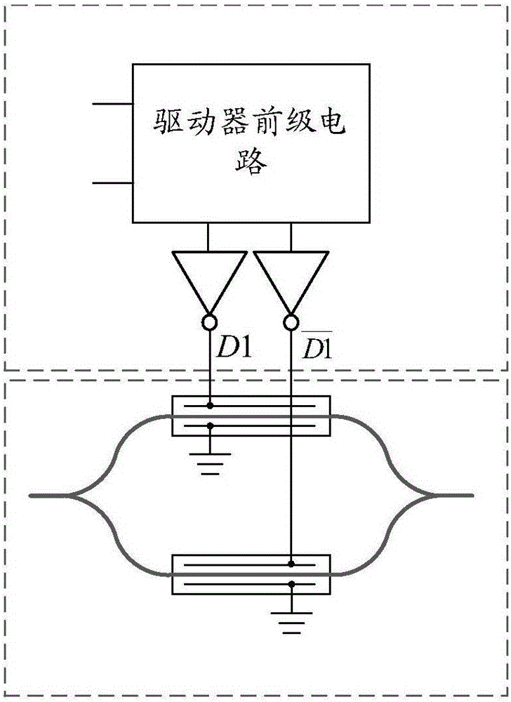
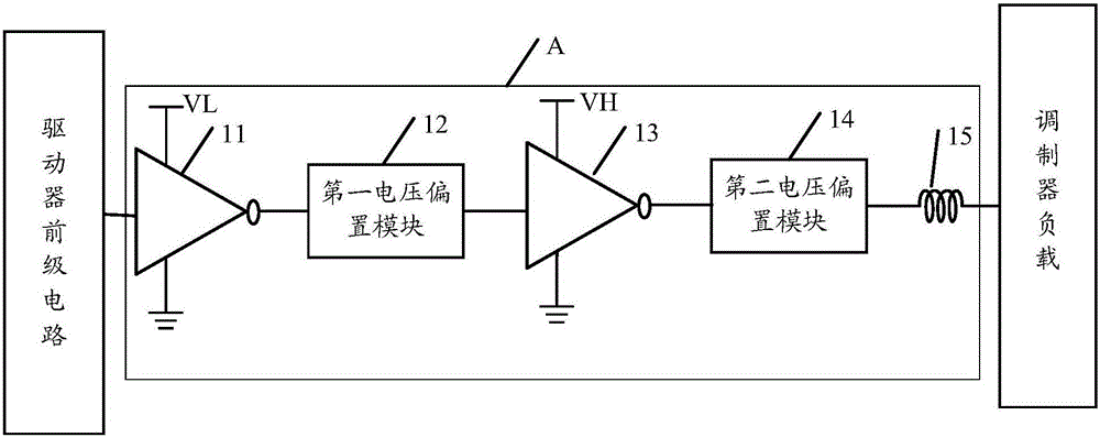
[0052] The embodiment of the invention discloses a high-speed and high-swing driver circuit suitable for a silicon light modulator. In the embodiment of the present invention, the signal output by the front-stage circuit of the driver is amplified and buffered, and the output full-scale digital signal enters the first inverter; the first inverter further buffers; the output signal of the first inverter passes through the first The voltage bias mo...


PUM


Abstract

An embodiment of the invention discloses a high-rate high-swing-amplitude driver circuit suitable for a silicon photo-modulator. The driver circuit is connected with a driver pre-stage circuit and a modulator load respectively and comprises at least one output circuit, each output circuit comprises a first phase inverter, a first voltage bias module, a second phase inverter, a second voltage bias module and an inductor, an input end of each first phase inverter is connected with an output end of the driver pre-stage circuit while an output end of the same is connected with an input end of the corresponding first voltage bias module, an output end of each first voltage bias module is connected with an input end of the corresponding second phase inverter, an output end of each second phase inverter is connected with an input end of the corresponding second voltage bias module, an output end of each second voltage bias module is connected with an input end of the corresponding inductor, and an output end of each inductor is connected with an input end of the modulator load. Through the driver circuit formed by circuit connection, high rate is guaranteed while output swing amplitude of a driver is increased.

Description

technical field [0001] The invention relates to the field of communication technology, in particular to a high-speed and high-swing driver circuit suitable for silicon light modulators. Background technique [0002] With the development of communication technology, the demand for information in modern society is increasing exponentially. In terms of short-distance communication, with the continuous reduction of chip size and continuous improvement of speed, traditional electrical interconnection technology is facing increased parasitic effects and limited transmission bandwidth. A series of bottlenecks such as the limitation, optical interconnection technology has become an ideal solution to replace metal interconnection because of its advantages of non-interference between different signal transmissions and huge bandwidth. In the field of optical interconnection technology, silicon photonics Technology is generally considered to be the key technology of the next generation....

Claims


Application Information

Patent Timeline
IPC IPC(8): H03K19/094
CPCH03K19/094G02F1/0123G02F1/21H03K19/0948G02F1/212
Inventor 朱文锐张德华赵磊
Owner HUAWEI TECH CO LTD
Why Eureka
Try Eureka