Spherical composite gas cylinder for spaceflight

A technology of composite materials and composite material layers, which is applied in the field of thin-walled metal lining/fiber winding composite gas cylinders, can solve the problems of increasing structural quality, immaturity of spherical composite gas cylinders, and reducing safety, and achieve structural quality The effect of small size, abundant types, optimized structure quality

Inactive Publication Date: 2016-06-15
SHANGHAI INST OF SPACE PROPULSION
View PDF3 Cites 7 Cited by
  • Summary
  • Abstract
  • Description
  • Claims
  • Application Information

AI Technical Summary

Problems solved by technology

[0005] However, some aerospace systems require spherical cylinders due to their special installation space constraints, but since spherical com

Method used


Image

  • Spherical composite gas cylinder for spaceflight
  • Spherical composite gas cylinder for spaceflight
  • Spherical composite gas cylinder for spaceflight

Examples


Embodiment 1

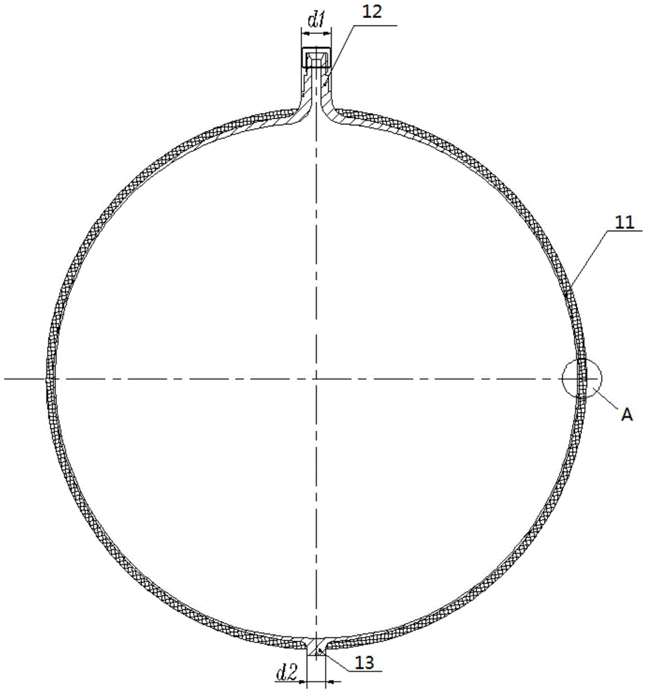
[0022] like Figure 1-2 shown, including the following steps:

[0023] Step 1: The metal lining 1 is composed of a spherical shell 11 , a nozzle 12 and a boss 13 , and the nozzle and the boss 13 are respectively located at the two ends of the axis of the spherical shell 11 .

[0024] Step 2: The material for preparing the metal lining 1 is aluminum alloy 6061, and the spherical shell 11, the nozzle 12 and the boss 13 constituting the metal lining 1 are integrally formed by stamping, spinning and machining processes, and seamlessly connected.

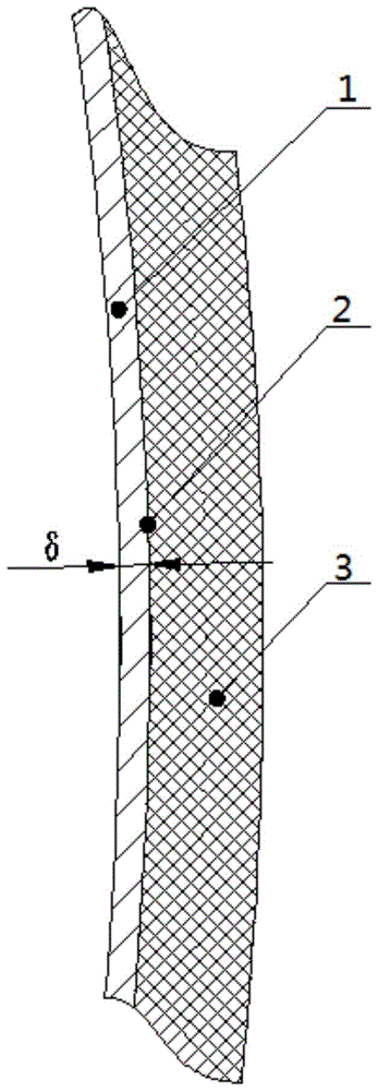
[0025] Step 3: The wall thickness of the thin film area of ​​the spherical shell 11 is equal, and the thickness gradually increases in the transition area between the spherical shell 11 and the connecting nozzle 12 and the boss 13 .

[0026] Step 4: The adhesive layer 2 is evenly laid on the outer surface of the spherical shell 11 according to the predetermined thickness, the purpose is to firmly connect the spherical shell 11 of the me...

Embodiment 2

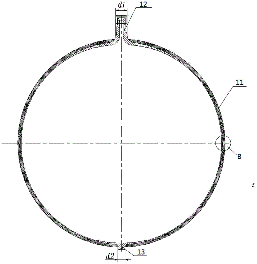
[0031] like Figure 3-4 shown, including the following steps:

[0032] Step 1: The metal lining 1 is composed of a spherical shell 11 , a nozzle 12 and a boss 13 , and the nozzle and the boss 13 are respectively located at the two ends of the axis of the spherical shell 11 .

[0033] Step 2: The material for preparing the metal lining 1 is one of titanium alloys TA0, TA1, TA2, TA3, TA4, TA5, TA6, TA7, TA8, TA9, TA10 and TC4, which constitute the spherical shell 11 of the metal lining 1 , The nozzle 12 and the boss 13 are formed by forging and machining, and welded and assembled at the equator of the spherical shell 11 of the metal lining 1.

[0034] Step 3: The wall thickness of the thin film area of ​​the spherical shell 11 is equal, and the thickness gradually increases in the transition area between the spherical shell 11 and the connecting nozzle 12 and the boss 13 .

[0035] Step 4: The adhesive layer 2 is evenly laid on the outer surface of the spherical shell 11 accor...


PUM


Abstract

The invention discloses a spherical composite gas cylinder for spaceflight. The spherical composite gas cylinder for spaceflight comprises a metal lining, an adhesive layer and a composite layer, wherein the adhesive layer is laid on the outer surface of the metal lining, and the composite layer is wound around the outer surface of the adhesive layer. The metal lining is composed of a spherical shell, a filler neck and a boss. The filler neck and the boss are located at the peaks of the two ends of the axis of the spherical shell correspondingly. Iso-wall thickness design is adopted in the thin film region of the spherical shell. Gradual-change thickness reinforcement design is adopted in the connection transition region of the spherical shell and the filler neck and the connection transition region of the spherical shell and the boss. The adhesive layer is evenly laid on the outer surface of the spherical shell, so that the spherical shell and the composite layer are firmly connected and prevented from making direct contact with each other. The spherical composite gas cylinder for spaceflight solves the problems that an existing composite gas cylinder is singular in structural form and a metal gas cylinder is low in structural efficiency, poor in installation space adaptability and the like. The spherical composite gas cylinder for spaceflight has the good beneficial effects of being low in structural mass, high in reliability, good in safety, high in space adaptability and the like.

Description

technical field [0001] The invention relates to a spherical gas cylinder for aerospace, in particular to a thin-walled metal lining / fiber wound composite material gas cylinder. Background technique [0002] Composite gas cylinders have been widely used in the aerospace field due to their high structural efficiency and safety failure mode of first leakage before explosion, and have become one of the most important stand-alone equipment in aerospace systems. With the continuous improvement of aerospace performance requirements for structural efficiency, reliability and safety, and the development of high-performance fiber winding materials and winding technology, it is just around the corner that composite material gas cylinders will completely replace metal material gas cylinders. [0003] The purpose of composite gas cylinders for aerospace is mainly to carry high-pressure gas media and provide working gas sources for aerospace systems. The development of composite gas cyli...

Claims


Application Information

Patent Timeline
IPC IPC(8): F17C1/06F17C13/00
CPCF17C1/06F17C13/00F17C2201/0128F17C2203/0604F17C2203/0636F17C2203/0663F17C2205/0305F17C2209/2154F17C2270/0186
Inventor 晏飞沈俊王婷婷陈军军田桂吴庆峰
Owner SHANGHAI INST OF SPACE PROPULSION
Why Eureka
Try Eureka