
Characteristic coincidence degree comparison method for onsite defect linear trace

A linear trace and coincidence technology, applied in the field of criminal investigation science, can solve the problems of high price and cost, loss, etc., and achieve the effect of improving efficiency and wide practicability

Active Publication Date: 2016-06-15
KUNMING UNIV OF SCI & TECH
View PDF2 Cites 3 Cited by
  • Summary
  • Abstract
  • Description
  • Claims
  • Application Information

AI Technical Summary

Problems solved by technology

[0004] At this stage, the commonly used judgment methods mostly use methods such as photo comparison and three-dimensional image forming, and then artificial comparison; these methods not only cause different degrees of loss in image collection, but also have high price and cost

Method used


Image

  • Characteristic coincidence degree comparison method for onsite defect linear trace
  • Characteristic coincidence degree comparison method for onsite defect linear trace
  • Characteristic coincidence degree comparison method for onsite defect linear trace

Examples


Embodiment 1

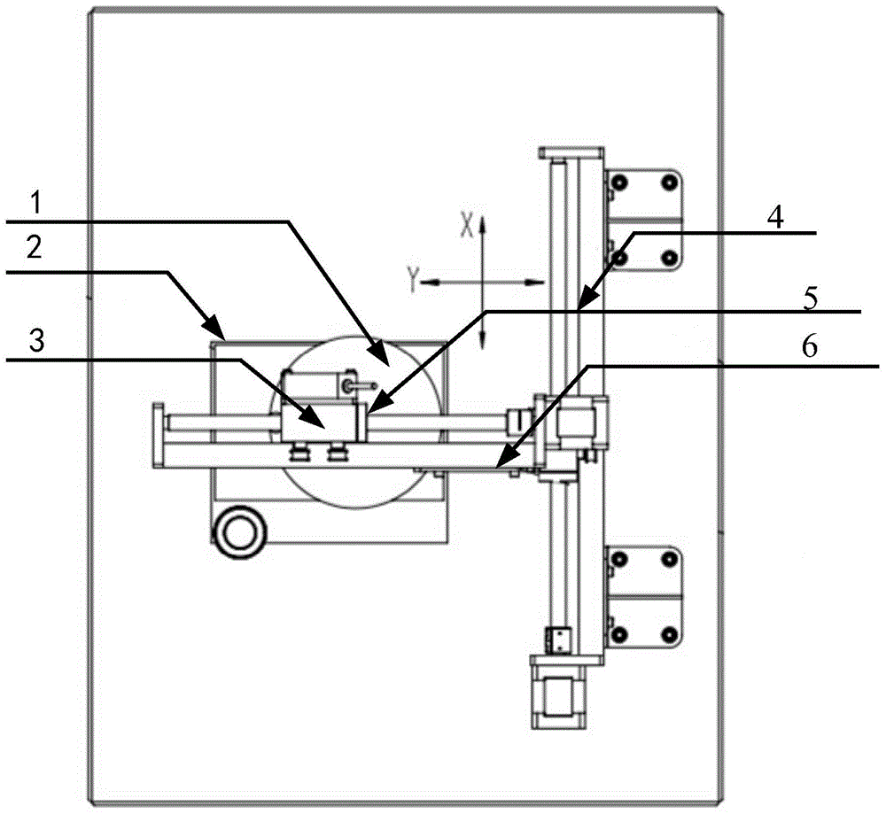
[0036] Embodiment 1: as Figure 1-7 As shown, a method for comparing the coincidence degree of incomplete linear trace features on the spot, the specific steps of the coincidence degree comparison method for the incomplete linear trace features on the spot are as follows:

[0037] Step 1. Use the laser displacement sensor of the linear trace laser detection test bench device to horizontally detect the incomplete linear trace surface on the trace bearing body to form a detection signal waveform f(x);

[0038] Step2. Through wavelet decomposition, the laser detection signal waveform f(x) is subjected to data smoothing processing to eliminate background noise interference and obtain a smoothed signal f 1 (x);

[0039] In the step Step2, the specific steps are:

[0040] Step2.1. Decompose the original signal into two parts according to the following formula:

[0041] f = a n + Σ i ...

Embodiment 2

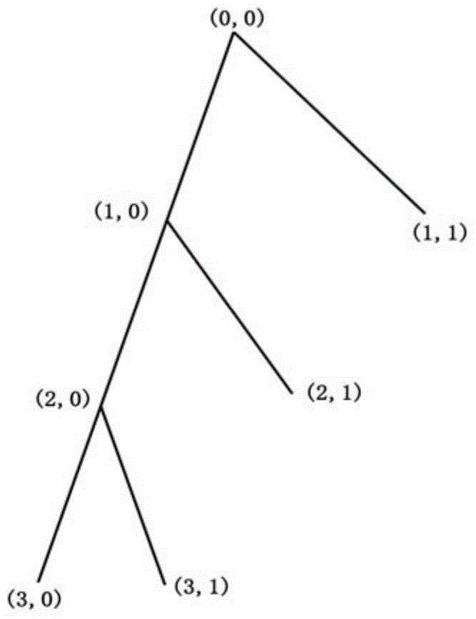
[0051] Embodiment 2: as Figure 1-7 As shown, a method for comparing coincidence degree of on-site incomplete linear trace features, this embodiment is the same as Embodiment 1, the difference is that this embodiment is explained with an actual case:

[0052] The specific steps of the on-site incomplete linear trace feature coincidence degree comparison method are as follows:

[0053] Step 1. Use the laser displacement sensor of the linear trace laser detection test bench device to horizontally detect the incomplete linear trace surface on the trace bearing body to form a detection signal waveform f(x);

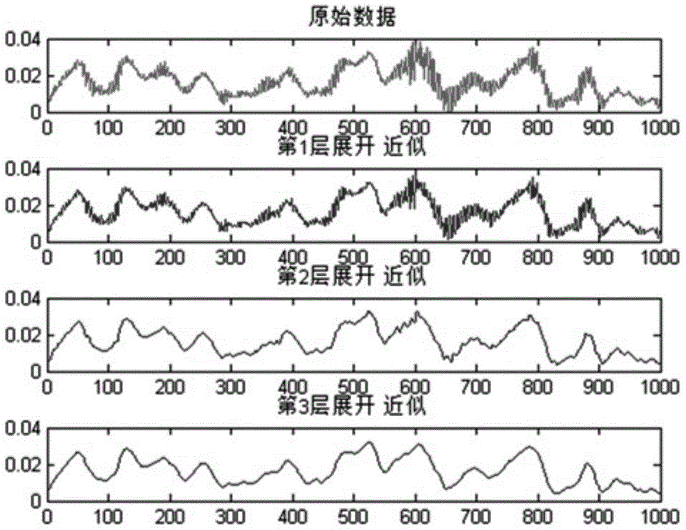
[0054] Step2. Through wavelet decomposition, the laser detection signal waveform f(x) is subjected to data smoothing processing to eliminate background noise interference and obtain a smoothed signal f 1 (x);

[0055] Such as Figure 2-3 As shown, in the actual noise reduction process, the original signal f(t) needs to be decomposed into multiple layers. The more layers ar...


PUM


Abstract

The invention relates to a characteristic coincidence degree comparison method for an onsite defect linear trace, and belongs to the technical field of criminal investigation science. A laser displacement sensor on a linear trace laser test stand device is used to detect the defect linear trace surface of a trace bearing body, discrete signal data is obtained, data which needs noise reduction is decomposed via wavelet transformation, a threshold is selected for noise reduction, macroscopic burrs are removed to complete noise reduction of the data, the trace characteristic is described by dividing trace signals into boxes according to a fixed plan in a gradient characteristic identification method, the ratio of the coincidence area of the trace signal and a sample signal to the total coverage area of the trace signal and the sample signals is calculated and serves as a result of coincidence degree comparison, and a linear trace sample most approximate to the liner trance to be detected is searched and considered as a criminal tool.

Description

technical field [0001] The invention relates to a method for comparing coincidence degrees of incomplete linear trace features on the spot, belonging to the technical field of criminal investigation. Background technique [0002] As we all know, the railway is an important infrastructure of the country, and it is also the main artery of national economic development, especially the rapid development of high-speed rail has made it a popular means of transportation and the backbone of the comprehensive transportation system; important role in development. [0003] The high-speed development of the railway has also brought some hidden dangers. Because there are a large number of high-quality communication cables along the railway, and there are great difficulties in the management along the railway, this has caused some criminals to steal cables. Phenomenon. For the theft of cables, cutting tools are often used to cut cables, leaving only the ends of the cutting type. How to ...

Claims


Application Information

Patent Timeline
Patent Type & Authority Applications(China)
IPC IPC(8): G01B11/02
CPCG01B11/02
Inventor 潘楠杨敬树羿泽光
Owner KUNMING UNIV OF SCI & TECH
Learn More