Method and system for correcting scanning range of piezoelectric ceramic tube scanner

A piezoelectric ceramic tube and scanning range technology, applied in the field of microscopy, can solve the problems of large thickness difference, large scanning range error, inaccuracy and reliability, etc., and achieve the effect of low cost and improved accuracy

Active Publication Date: 2016-06-15
BEING NANO INSTR LTD
View PDF7 Cites 5 Cited by
  • Summary
  • Abstract
  • Description
  • Claims
  • Application Information

AI Technical Summary

Problems solved by technology

Probes are consumables in scanning probe microscopes. At present, the probes have basically achieved generalized mass production, and their geometric shapes are very consistent, and the length of the probes is basically unchanged. There are many varieties and the difference in thickness is very large, which leads to a large error in the actual scanning range. If the correction can not be made in time according to the corresponding thickness, it will directly affect the accuracy of the detection results.
[0009] However, the current piezoceramic tube-type scanning microscope, whether it adopts the existing open-loop calibration method or closed-loop calibration method, detects the movement of the piezoelectric ceramic tube scanner sample stage instead of the sample movement, and all The thickness of the sample is the thickness of the standard sample by default, and the scanning range error caused by the difference in sample thickness cannot be calibrated, which is not accurate and reliable enough

Method used


Image

  • Method and system for correcting scanning range of piezoelectric ceramic tube scanner
  • Method and system for correcting scanning range of piezoelectric ceramic tube scanner
  • Method and system for correcting scanning range of piezoelectric ceramic tube scanner

Examples


Embodiment 1

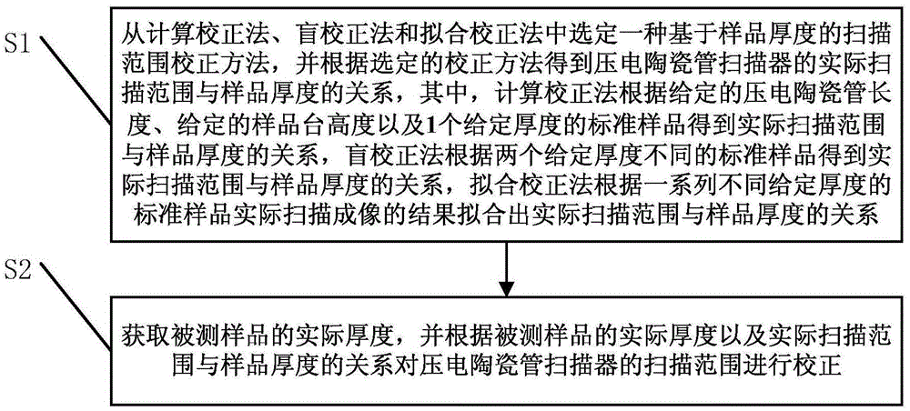
[0089] This embodiment describes the basic principles of the present invention and related theories involved.

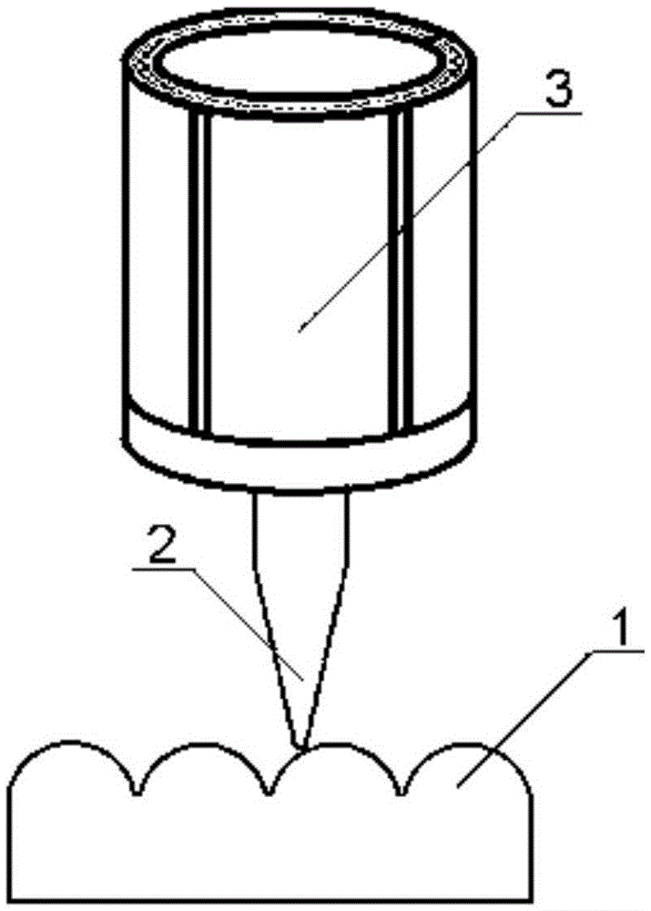
[0090] The scanning probe microscope controls the probe to scan the surface of the sample through the piezoelectric scanner, and simultaneously detects and records the interaction signal between the probe and the sample, so as to obtain the surface information of the sample. Probe-to-sample scanning is actually a controllable relative movement between the probe and the sample, which can be done by either probe scanning or sample scanning, such as image 3 and 4 shown.

[0091] image 3 and 4 Among them, 1 is the sample to be tested, 2 is the probe, 3 is the piezoelectric scanner, image 3 is the probe scanning method, Figure 4 It is the sample scanning mode. In fact, the scanning motion of the probe and the sample is the relative motion of the two. These two methods are equivalent, but the current scanning probe microscope generally integrates a variety of det...

Embodiment 2

[0129] In order to improve the automation of the scanning probe microscope and make it more convenient for users to use, for the scanning probe microscope, the present invention proposes a technology for automatically measuring the thickness of the sample. This technology is combined with the scanning range correction method of the first embodiment. When the sample is tested, the thickness of the sample can be obtained automatically, and the automatic online correction of the scanning range can be realized.

[0130] The structure of the scanning probe microscope probe used for automatic measurement such as Figure 11 shown. Figure 11 Among them, 12 is a measuring head, 5 is a base, 2 is a probe, 3 is a scanner, 1 is a sample, 13 is a precision screw, and 14 is a stepping motor. The scanning probe microscope scans the surface of the sample by the probe in the probe controlled by the system to obtain the surface information of the sample. The probe is mainly composed of a meas...


PUM


Abstract

The invention discloses a method and system for correcting the scanning range of a piezoelectric ceramic tube scanner, and the method comprises the steps: selecting one scanning range correction method based on sample thickness from a calculation correction method, a blind correction method and a fitting correction method, and obtaining the relation between the actual scanning range of the piezoelectric ceramic tube scanner and the sample thickness; obtaining the actual thickness of a tested sample, and correcting the scanning range of the piezoelectric ceramic tube scanner according to the actual thickness of the tested sample and the relation between the actual scanning range and the sample thickness. According to the invention, the calculation correction method, the blind correction method and the fitting correction method are added, and the method can obtain the relation between the actual scanning range and the sample thickness, corrects the scanning range according to the actual thickness of the sample, effectively corrects the change, caused by the change of the sample thickness, of the scanning range of the piezoelectric ceramic tube scanner, and is more accurate and reliable. The method can be widely used in the technical field of microscopes.

Description

technical field [0001] The invention relates to the technical field of microscopes, in particular to a scanning range correction method and system for a piezoelectric ceramic tube scanner. Background technique [0002] Since the appearance of the scanning tunneling microscope (STM) in 1982, a series of new microscopy techniques with similar working principles have been developed, including atomic force microscopy (AFM), lateral force microscopy (LFM), magnetic force microscopy (MFM), static Electric force microscopy (EFM), near-field optical microscopy (SNOM), piezoelectric force microscopy (PFM), scanning probe acoustic microscopy (SPAM), etc., because they all use probes to scan the sample to be tested, while detecting The interaction between the probe and the sample (such as the interaction force between the sample and the probe, etc.), and the related properties of the sample (such as morphology, friction, magnetic domain structure, etc.) are obtained, so it is collectiv...

Claims


Application Information

Patent Timeline
Patent Type & Authority Applications(China)
IPC IPC(8): G01Q40/00
CPCG01Q40/00
Inventor 吴浚瀚
Owner BEING NANO INSTR LTD
Why Eureka
Try Eureka