Heat treatment waste gas plasma recombination power generation method and plasma recombination reactor

A technology of reactor and heat treatment equipment, which is applied in the field of heat treatment waste gas treatment, and can solve problems such as surface potential drop and application limitations

Active Publication Date: 2016-06-22
KMC CHAIN TAICANG CO LTD
View PDF5 Cites 2 Cited by
  • Summary
  • Abstract
  • Description
  • Claims
  • Application Information

AI Technical Summary

Problems solved by technology

[0010] (5) Radio frequency (radiofrequency) discharge system: The electrodes in the DC plasma source are given a layer of insulating material. Due to t

Method used


Image

  • Heat treatment waste gas plasma recombination power generation method and plasma recombination reactor
  • Heat treatment waste gas plasma recombination power generation method and plasma recombination reactor
  • Heat treatment waste gas plasma recombination power generation method and plasma recombination reactor

Examples


Embodiment 1

[0050] The operation example 1 of the low energy consumption normal temperature plasma recombination equipment is as follows:

[0051] a. The reaction chamber will be evacuated to a vacuum state, reaching 4X10 -5 atm (1x10 -5 -5x10 -5 between atm)

[0052] b. Introduce reaction gas (propane C 3 h 8 and nitrogen N 2) And control the intake flow, and confirm that the gas flow range of the oil pump output is 20-200mL / min.

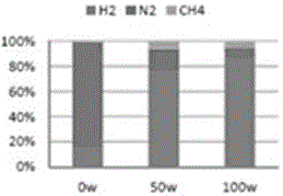
[0053] c. After the atmosphere in the reaction chamber is stable, reach 3X10 -3 Atm, turn on the RF plasma source and matcher, and control the matching conditions to achieve the best power. The power setting range is between 50W-200W.

[0054] d Collect reaction gas samples, use GC to analyze and record the proportions of its various components, see image 3 .

Embodiment 2

[0056] The operation example 2 of the low energy consumption room temperature plasma recombination equipment is as follows:

[0057] a. First pump the reaction chamber to a vacuum state, reaching 3.67X10 -3 atm.

[0058] b. Introduce reaction gas (methane CH 4 and nitrogen N 2) And control the intake flow, and confirm that the gas flow range of the dry vacuum pump is 20-200mL / min.

[0059] c. The atmosphere in the reaction chamber is stable up to 6X10 -2 After atm, turn on the RF plasma source and matcher, and control the matching conditions to achieve the best power. The power setting range is between 25W-125W.

[0060] d Collect reaction gas samples, use GC to analyze the proportion of hydrogen gas under various plasma power conditions, and calculate the conversion rate of methane, see Figure 4 and Figure 5 .


PUM


Abstract

The invention provides a heat treatment waste gas plasma recombination power generation method and a plasma recombination reactor.The heat treatment waste gas plasma recombination power generation method comprises the following technical steps that 1, tail gas of heat treatment equipment is generated; 2, the tail gas of the heat treatment equipment is pretreated; 3, the pretreated tail gas is guided into the plasma recombination reactor for a recombination reaction; 4, gas prepared in the step 3 is guided into a gas turbine generator for power generation.The heat treatment waste gas plasma recombination power generation method and the plasma recombination reactor have the advantages that an existing traditional treatment technique-waste gas burning is replaced with a plasma recombination treatment technique on the basis of a target of a factory on heat treatment waste gas energy regeneration, the heat treatment waste gas can be effectively recombined into energy gas under the normal temperature condition by adopting low-energy consumption radiofrequency plasma to cooperate with a nanometal catalyst, the energy gas is connected to the gas turbine generator for power generation by cooperating with improvement of a power generator, and therefore the effects of low carbon emission and energy regeneration are simultaneously achieved.

Description

technical field [0001] The invention relates to a treatment method for heat treatment waste gas, in particular to a method for heat treatment waste gas plasma recombination power generation, and a plasma recombination reactor. Background technique [0002] Heat treatment is to heat steel or other metal materials to a certain temperature in a solid state and then cool them to change their physical and mechanical properties. There are many heat treatment methods, usually represented by quenching, annealing and tempering, which mainly change the normal temperature structure of metal or steel materials into the physical and mechanical properties required for processing through heating, cooling, bathing and other processes. , and the environmental conditions of the treatment are mainly controlled by the gas atmosphere and temperature in the heat treatment furnace. In order to ensure the stability of the product, the adjusted gas must be continuously sent into the furnace during t...

Claims


Application Information

Patent Timeline
IPC IPC(8): B01D53/32B01D50/00B01D46/00B01D47/00C10L3/00C10L3/08C01B3/24C07C9/04
CPCB01D46/00B01D47/00B01D53/32C10L3/00C10L3/08C01B3/24C07C9/04B01D50/60Y02P70/10
Inventor 吴厚德邱国峰吕晃明
Owner KMC CHAIN TAICANG CO LTD
Why Eureka
Try Eureka