Efficient electrostatic dust collector

An electrostatic precipitator and precipitator technology, applied in the direction of electrostatic separation, particle charging/ionization places, etc., can solve the problems of large volume, high cost, low dust removal efficiency, etc., achieve small size, save space, and improve dust removal efficiency Effect

Active Publication Date: 2016-06-22
HUBEI QIANGDA ENVIRONMENTAL PROTECTION TECH CO LTD
View PDF10 Cites 8 Cited by
  • Summary
  • Abstract
  • Description
  • Claims
  • Application Information

AI Technical Summary

Problems solved by technology

[0004] The purpose of the present invention is to solve the problems of large volume, high cost and low dust removal efficiency of existing electrostatic precipitators, and to provide a high-efficiency electrostatic precipitator

Method used


Image

  • Efficient electrostatic dust collector
  • Efficient electrostatic dust collector
  • Efficient electrostatic dust collector

Examples


Embodiment 1

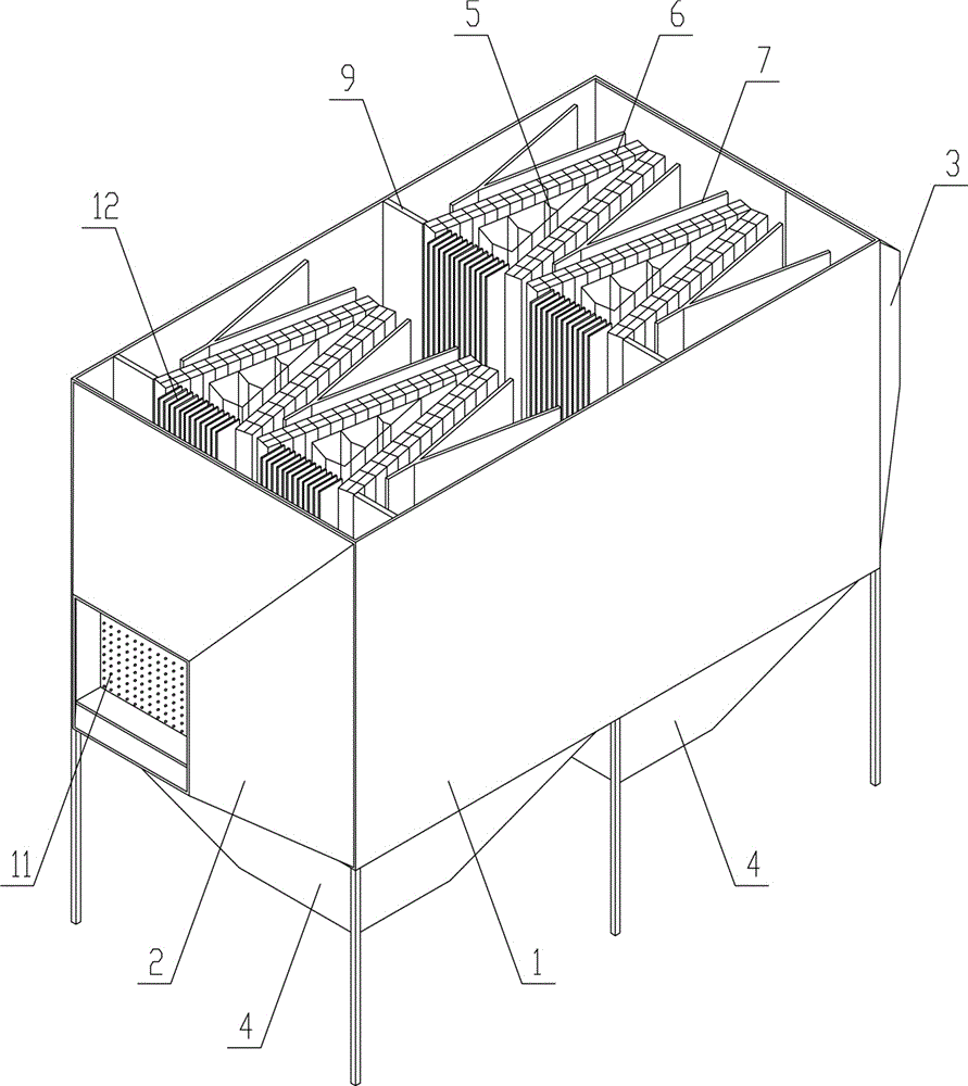
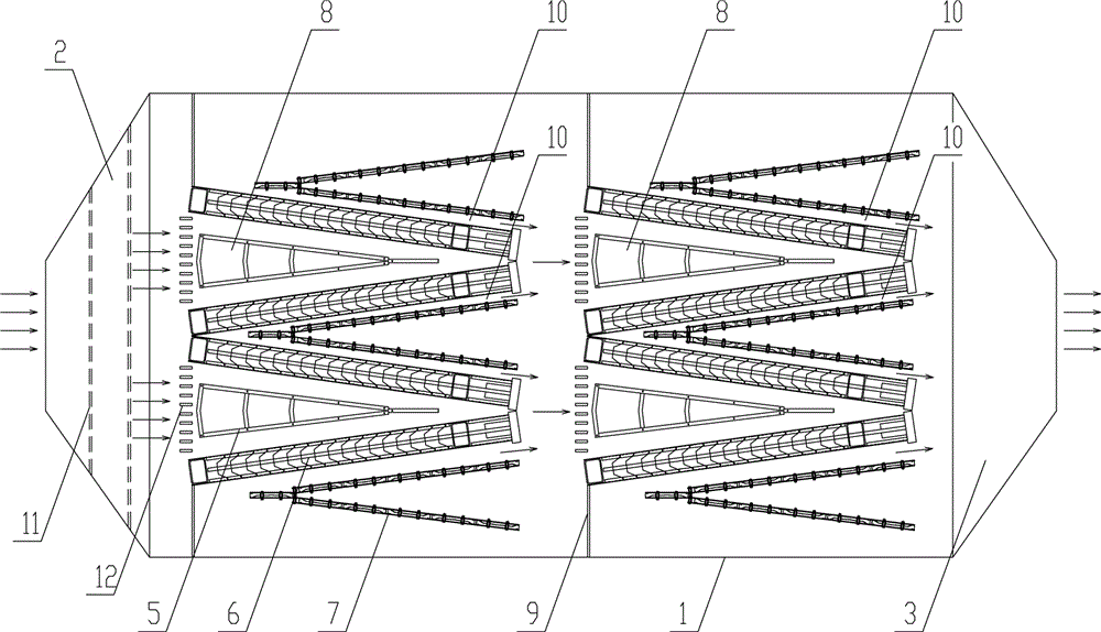
[0018] see figure 1 , figure 2 , the present invention includes a dust collector body 1, an inlet head 2, an outlet head 3 and an ash collecting hopper 4, the inlet head 2 and the outlet head 3 are correspondingly arranged at the inlet end and the outlet end of the dust collector body 1, and the dust collector body The dust collection bucket 4 is arranged at the bottom of 1; several groups of electric field structures are arranged from the inlet end to the outlet end of the dust collector body 1, and each group of electric field structures includes several groups of three-electrode breeze dust removal units arranged side by side, and each group has three The electrode breeze dust removal unit has a cathode suspension 5, left and right louver plates 6 are arranged on both sides of the cathode suspension 5, and left and right anode plates 7 are arranged on the outside of the two louver plates, wherein the anode plate 7. The potentials of the louver plates 6 and the cathode sus...

Embodiment 2

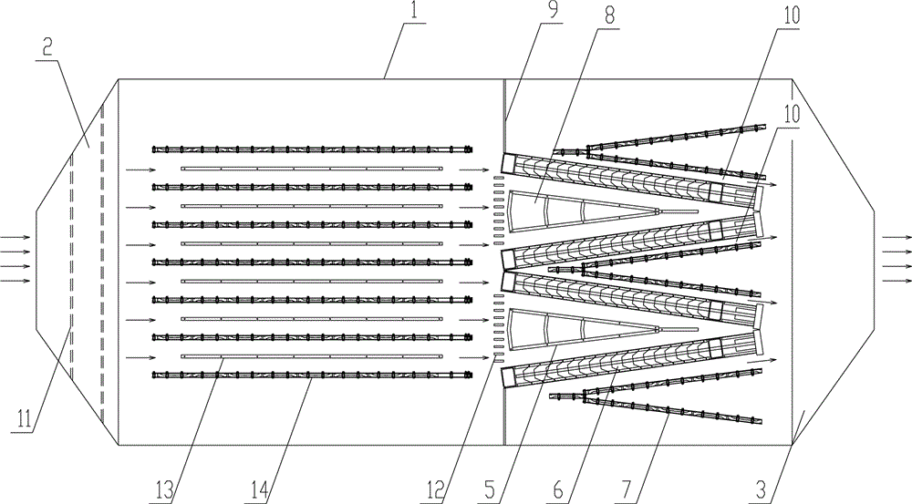
[0027] see image 3 , this embodiment makes improvements on the basis of Embodiment 1, the difference is that: the electric field structure described in this embodiment also includes several groups of two-electrode dust removal units arranged side by side, and the two electrode dust removal units are composed of cathode suspension 13 and Composed of anode plate 14; two electric field structures with two-electrode dust removal unit and three-electrode breeze dust removal unit are combined and arranged in the dust collector body 1, and the flow direction of the dust-laden flue gas in the dust collector is as follows: image 3 shown.


PUM


Abstract

The invention discloses an efficient electrostatic dust collector which comprises a dust collector body, an inlet seal, an outlet seal and an ash collection hopper. A plurality of sets of electric field structures are distributed on the dust collector body from the inlet end to the outlet end. Each set of electric field structure comprises a plurality of sets of three-electrode breeze dedusting units distributed side by side. Each set of three-electrode breeze dedusting unit is composed of a cathode suspension rack, a left shutter polar plate, a right shutter polar plate, a left anode plate and a right anode plate, wherein the anode plates, the shutter polar plates and the cathode suspension rack form a two-stage electric field structure; in each set of three-electrode breeze dedusting unit, an air flue inlet is formed between the left shutter polar plate and the right shutter polar plate; the ends, facing the outlet side of the dust collector body, of the left shutter polar plate and the right shutter polar plate are connected with each other; and an air flue outlet is formed between each shutter polar plate and the corresponding anode plate adjacent to the shutter polar plate. The efficient electrostatic dust collector is small in size and low in production input cost, the flow velocity of dust-contained flue gas is greatly decreased, the dust duration time is prolonged, the dust deposition effect is enhanced, and the dust collection efficiency is effectively improved.

Description

technical field [0001] The invention relates to the technical field of electrostatic precipitators, in particular to a high-efficiency electrostatic precipitator. Background technique [0002] At present, the dust particles in the flue gas emitted by various large enterprises such as coal-fired power plants, steel mills, paper mills, and cement plants are important sources of pollution that cause various extreme smog weather. With the increasingly serious environmental pressure, there are very strict requirements on the emission of dusty flue gas. [0003] The electrostatic precipitator technology used in the electrostatic precipitator, as one of the dust removal technologies with broad application prospects, has been widely used in the environmental protection industry. The electrostatic precipitator includes a precipitator body, an inlet head, an outlet head and a dust collecting hopper. fight. There are several sets of electric field structures between the inlet and th...

Claims


Application Information

Patent Timeline
Patent Type & Authority Applications(China)
IPC IPC(8): B03C3/38
CPCB03C3/38
Inventor 刘方兵王文洲张友尧伍仪寿柯军
Owner HUBEI QIANGDA ENVIRONMENTAL PROTECTION TECH CO LTD
Why Eureka
Try Eureka