Efficient and energy-saving air compression environmental protection device

An air compression and environmental protection device technology, applied in the field of compressed air compression, can solve the problems of large volume and low working efficiency of air compressors

Inactive Publication Date: 2016-06-22
任雪颖
View PDF0 Cites 2 Cited by
  • Summary
  • Abstract
  • Description
  • Claims
  • Application Information

AI Technical Summary

Problems solved by technology

[0002] The traditional air compressor uses the air compressor of the crank connecting rod mechanism to compress

Method used


Image

  • Efficient and energy-saving air compression environmental protection device
  • Efficient and energy-saving air compression environmental protection device
  • Efficient and energy-saving air compression environmental protection device

Examples


Embodiment Construction

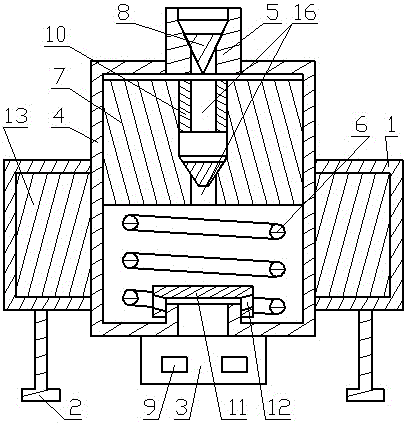
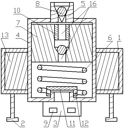
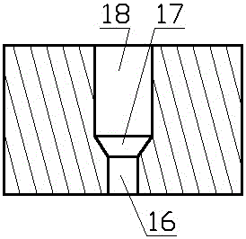
[0057] The high-efficiency energy-saving air compression environmental protection device of the present invention mainly includes a protective shell 1, an electromagnetic coil 13, an air pump shell 4, an air intake hole, a sealing ball 8 or a sealing cone 8, a sealing cap 11, an iron core spring 6, a magnetic piston 7, and a fixed plug 10. Inner taper hole 17, vent hole 16, air outlet valve, air filter 3, magnetic field controller, electronic remote control device; or include protective shell 1, electromagnetic coil 13, air pump shell 4, air inlet hole, sealing ball 8 or Sealing cone 8, sealing cap 11, iron core spring 6, magnetic piston 7, fixed plug 10, inner cone hole 17, vent hole 16, air outlet valve, air filter 3, magnetic field controller.

[0058] An electromagnetic coil 13 is installed in the protective shell 1, and the electromagnetic coil 13 is fixed on the lower part outside the air pump shell 4, and the protective shell 1 is fixed on the outside of the lower part o...


PUM


Abstract

A high-efficiency energy-saving air compression environmental protection device, which belongs to air equipment; its electromagnetic coil is outside the air pump casing, the protective casing is fixed on the air pump casing, the filter is fixed at the air intake hole at the lower end of the air pump casing; the air outlet valve is fixed on the air pump In the center hole of the shell, there is an iron core spring and a magnetic piston in the air pump shell. The iron core spring presses against the lower end surface of the magnetic piston. The air inlet channel of the pressure chamber; a fixed plug is fixed in the plug hole in the magnetic piston, and a sealing ball or sealing cone is installed in the inner cone hole. The high-efficiency energy-saving air compression environmental protection device has compact structure, low vibration, high power utilization rate, strong power, and high efficiency of compressed air. It is suitable for installation and use of electric vehicles and internal combustion engine vehicles with pneumatic brakes, and is also suitable for use with pneumatic cylinders. When used together, it is also suitable for the combined use of painting equipment; the market prospect of industrialization is good, the commercial value is high, and the manufacture and use are very convenient.

Description

technical field [0001] The invention relates to a high-efficiency energy-saving air compression environmental protection device in the field of compressed air compression. Background technique [0002] The traditional air compressor uses the air compressor of the crank linkage mechanism to compress air, and the air compressor of the crank linkage mechanism has a large volume and low working efficiency. For this reason, we have designed an air compression device with small volume and high efficiency of compressing air. Contents of the invention [0003] The purpose of the present invention is to provide a high-efficiency energy-saving air compression environmental protection device with high utilization rate of electric energy and high-efficiency compressed air and a method thereof. [0004] In order to achieve the above object, the high-efficiency energy-saving air compression environmental protection device of the present invention mainly includes a protective shell, an ...

Claims


Application Information

Patent Timeline
IPC IPC(8): F04B35/04F04B39/00F04B39/10F04B39/12F04B39/16F04B39/14F04B49/06
CPCF04B35/04F04B39/0005F04B39/0016F04B39/1006F04B39/1013F04B39/1026F04B39/121F04B39/14F04B39/16F04B49/06
Inventor 徐伟正任雪颍
Owner 任雪颖
Why Eureka
Try Eureka