
Wear-resistant brake line

A brake line and wear-resistant technology, applied in the field of wear-resistant brake lines and bicycle brake systems, can solve the problems of insufficient friction and support, insufficient brakes, and hidden safety hazards, and achieve increased friction and support, It is not easy to slide relative to each other, and the effect of using the effect is guaranteed

Inactive Publication Date: 2016-06-22
李士清
View PDF0 Cites 1 Cited by
  • Summary
  • Abstract
  • Description
  • Claims
  • Application Information

AI Technical Summary

Problems solved by technology

[0002] The bicycle brake system includes accessories such as brake handles, brake lines, and brake calipers. The brake system of the prior art is usually provided with a front and a rear brake line and two corresponding brake handles and two brake calipers. The brake line is prone to breakage after being used for a period of time, causing brake failure and high potential safety hazards. In order to solve the above technical problems, it is necessary to use a two-line brake system with two front brake lines and two rear brake lines. The two brake lines of this brake system The length of the two front brake cables must be the same to ensure that the two brake cable bodies are evenly stressed during braking. However, the two independent brake cable bodies cannot guarantee the same length, and there are certain difficulties in assembly.
[0003] The existing brake line body is composed of an outer rubber hollow tube and an inner steel wire, its strength is not high enough, its chemical corrosion resistance is poor, its weather resistance is not good, and its production cost is relatively high
[0004] The friction and supporting force between the inner liner and the outer cladding of the existing brake line are not enough, and the inner liner and the outer sheath tend to slide relative to each other, which will cause the brake to not be tight and affect the use effect of the braking system

Method used


Image

  • Wear-resistant brake line
  • Wear-resistant brake line
  • Wear-resistant brake line

Examples


Embodiment Construction

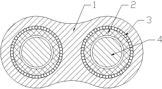
[0023] see figure 1 , the present invention relates to a wear-resistant brake line, comprising an outer cladding 1, two liner tubes 2 arranged side by side in parallel and a metal wire group 3, the lengths of the two liner tubes 2 are equal, and the liner tube 2 is provided with The brake line body 4, the metal wire group 3 includes a plurality of metal wires, the metal wires are closely arranged on the outer wall of the inner lining pipe 2, the length direction of the metal wires is consistent with the axial direction of the inner lining pipe 2, and the plurality of metal wires are arranged along the It is bent in a spiral shape in the length direction (similar to a twisted steel wire rope). The metal wire group 3 has 15 to 25 metal wires, preferably 21 wires. The outer cladding 1 is covered on the metal wire group 3 outside.

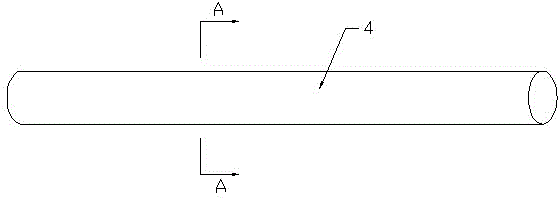
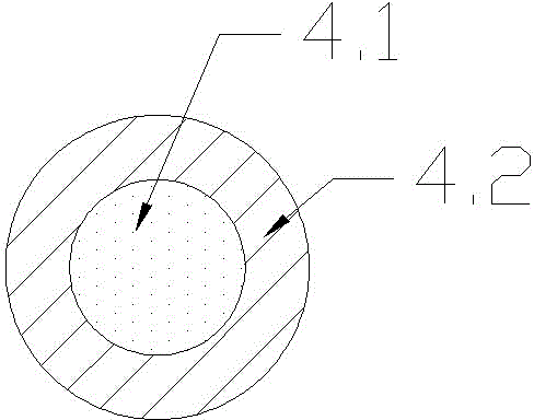
[0024] see Figure 2-3 , the brake line body 4 includes an inner layer of carbon fiber core wire group 4.1 and an outer layer of wear-resistant coat...


PUM


Abstract

The present invention relates to a wear-resistant brake line which comprises an outer cladding layer (1), two lining tubes (2) side by side disposed in parallel and two metal wire groups (3), a brake line body (4) comprises an inner layer carbon fiber core line group (4.1 ) and an outer layer wear-resistant coating (4.2). The lining tubes can ensure two brake lines are equal in length so as to ensure that two brake line bodies are uniformly forced in braking; the brake line body is simple in molding, light in weight, chemical-resistant, good in weather resistance and low in cost of production; the wear-resistant brake line effectively increases the frictional force and the support force between the lining tubes and the cladding layer, the lining tubes and the cladding layer are less prone to relative sliding, and the used effect of the brake system can be ensured.

Description

technical field [0001] The invention relates to a wear-resistant brake line, which is used in a bicycle brake system. It belongs to the field of bicycle accessories. Background technique [0002] The bicycle brake system includes accessories such as brake handles, brake lines, and brake calipers. The brake system of the prior art is usually provided with a front and a rear brake line and two corresponding brake handles and two brake calipers. The brake line is prone to breakage after being used for a period of time, causing brake failure and high potential safety hazards. In order to solve the above technical problems, it is necessary to use a two-line brake system with two front brake lines and two rear brake lines. The two brake lines of this brake system The length of the two front brake cables needs to be the same to ensure that the two brake cable bodies are evenly stressed during braking. However, the two independent brake cable bodies cannot guarantee the same length...

Claims


Application Information

Patent Timeline
IPC IPC(8): F16C1/10B62L3/00C09D133/00C09D7/12
Inventor 李士清
Owner 李士清
Learn More