A kind of cw-mfc coupling system and its degradation method for azo dye degradation

An azo dye and coupling system technology, applied in chemical instruments and methods, water pollutants, water/sludge/sewage treatment, etc., can solve the problems of toxicity, limited capacity of the cathode area of ​​the coupling device, and increased organic concentration. Achieve the effect of structure and performance optimization, reduction of hydraulic retention time, and simple operation

Inactive Publication Date: 2018-12-28
HOHAI UNIV
View PDF4 Cites 0 Cited by
  • Summary
  • Abstract
  • Description
  • Claims
  • Application Information

AI Technical Summary

Problems solved by technology

[0005] However, during the decolorization process of azo dyes, the traditional CW-MFC system cannot effectively remove the aromatic amines produced by the degradation of azo dyes due to the concentration of dissolved oxygen in the cathode area of ​​the coupling device and the limited treatment capacity. Water containing more toxic products and possible elevated concentrations of organics

Method used


Image

  • A kind of cw-mfc coupling system and its degradation method for azo dye degradation
  • A kind of cw-mfc coupling system and its degradation method for azo dye degradation
  • A kind of cw-mfc coupling system and its degradation method for azo dye degradation

Examples


Embodiment 1

[0047] The experimental design is as follows:

[0048] The purpose of the experiment: To study the ability and effect of this system when dealing with azo dyes with different types and differences in structure. The target pollutants of this experiment are reactive brilliant red X-3B and Congo red as examples.

[0049] Dye profile:

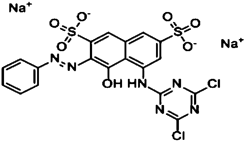
[0050] The chemical structure of Reactive Brilliant Red X-3B is:

[0051]

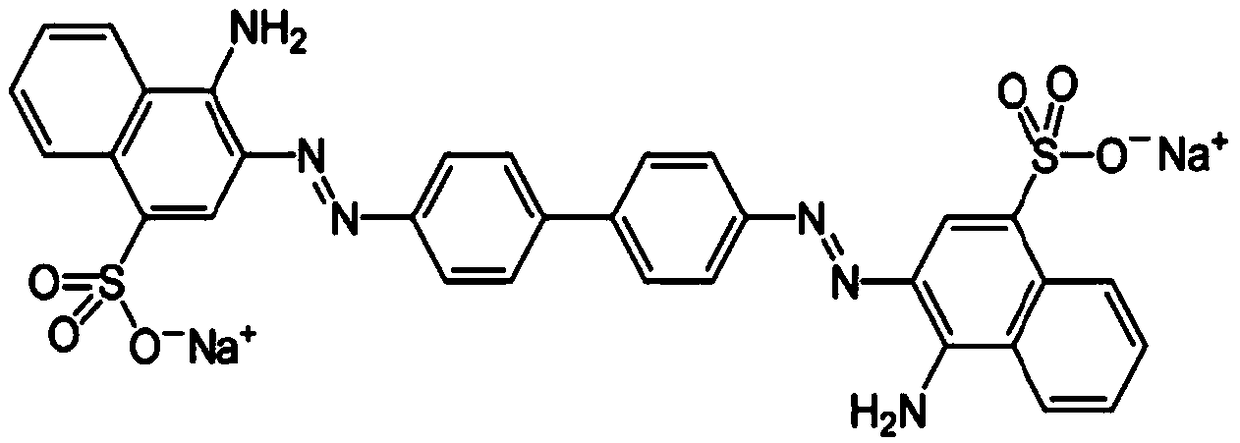
[0052] The chemical structure of Congo red is:

[0053]

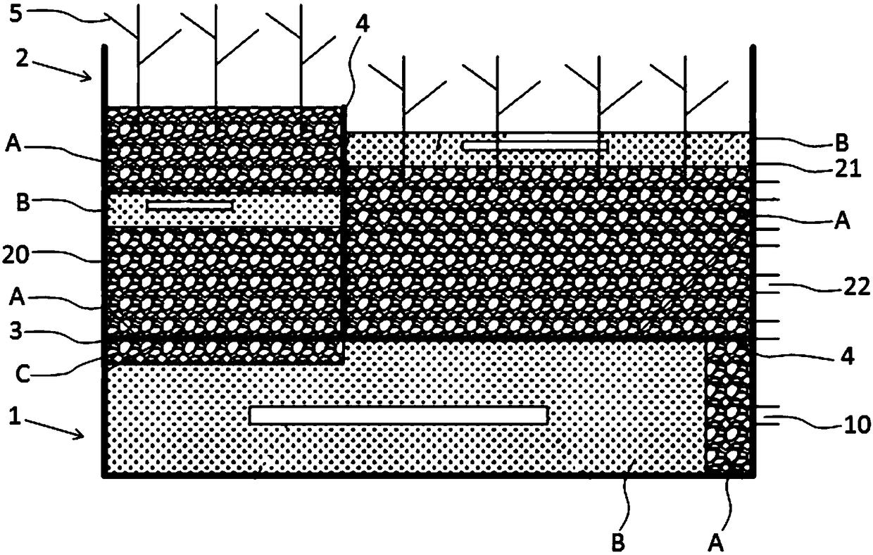
[0054] Experimental parameters: the volume ratio of the first cathode region 20 to the second cathode region 21 is 5:5, the hydraulic retention time HRT is 3d, and the continuous water inlet operation mode is adopted.

[0055] Experimental content: The concentrations of Reactive Brilliant Red X-3B and Congo in the influent of the two comparative experiments were both 100-300mg / L; glucose was selected as the co-substrate, and the concentration of glucose in the influent was 120mg / L.

[0056] The experimental ...

Embodiment 2

[0058] The experimental design is as follows:

[0059] Purpose of the experiment: adjust the volume ratio of the first cathode area 20 to the second cathode area 21, and determine the optimal concentration range and optimal HRT of the target pollutants that can be treated under different volume ratios. The target pollutants in this experiment are active dyes Take the red X-3B as an example.

[0060] Dye profile:

[0061] The chemical structure of Reactive Brilliant Red X-3B is:

[0062]

[0063] Experimental parameters: the volume ratios of the first cathode area 20 and the second cathode area 21 are set to 3:7, 5:5, and 7:3 respectively, the HRT is 2, 3, and 4d, and the continuous water inlet operation mode is adopted.

[0064] Experimental content: the volume ratios of the first cathode region 20 and the second cathode region 21 in the three comparative experiments were 3:7, 5:5, and 7:3 in sequence; the reactive brilliant red X- 3B corresponds to three concentration r...


PUM

PropertyMeasurementUnit
particle diameteraaaaaaaaaa
widthaaaaaaaaaa
widthaaaaaaaaaa

Abstract

The invention discloses a CW-MFC coupling system for azodye degradation and a degradation method thereof. The CW-MFC coupling system comprises an anode region at a lower layer and a cathode region at an upper layer; the cathode region is divided into a first cathode region and a second cathode region, the first cathode region and the anode region are in permeable connection, the second cathode region and the first cathode region and the anode region are in impermeable adjoining; the anode region is provided with a water inlet and a water inlet valve, the second cathode region is provided with a plurality of water outlets and water outlet valves; the cathode region of the system is planted with emergent aquatic plants; the volume ratio of the first cathode region and the second cathode region is between 3:7 to 7:3, the water current flowing through the first cathode region enters the second cathode region in a drop manner; a permeable baffle is arranged between the first cathode region and the anode region; and the impermeable baffles are arranged between the second cathode region and the first cathode region and between the second cathode region and the anode region. The system disclosed by the invention is simple in structure, optimized in cathode performance, and capable of completely and sufficiently degrading the azodye.

Description

technical field [0001] The invention belongs to the technical field of energy and water treatment, and in particular relates to a coupling system of an artificial wetland and a microbial fuel cell for the degradation of azo dyes and a degradation method thereof. Background technique [0002] In recent years, with the improvement of people's quality of life, the printing and dyeing and dyeing industries have developed rapidly, the number and variety of dyes have continued to increase, and the environmental pollution caused by printing and dyeing wastewater has become increasingly serious. According to reports, about 20% to 30% of dyes are released into the environment during production and use. The pollution of azo dyes is characterized by a large amount of pollution. Even if the concentration is very low, it can reduce the light transmittance of the water body and change the ecosystem of the water body. Moreover, the aromatic amine compounds decomposed from the azo dyes are ...

Claims


Application Information

Patent Timeline
Patent Type & Authority Patents(China)
IPC IPC(8): C02F3/32C02F3/30
CPCC02F3/301C02F3/32C02F2101/308
Inventor 赵联芳朱丹丹朱铁松谭少文贺丽谢梅香
Owner HOHAI UNIV
Why Eureka
Try Eureka