Supercharge Your Innovation With Domain-Expert AI Agents!

Oil pipe thread size parameter detection method and device

A thread size and parameter detection technology, which is applied to the digital image acquisition of parts, common thread and other parts size detection fields, can solve the problems of easy wear of the probe, low degree of automation, cumbersome operation, etc., to achieve precise processing and low device cost , the effect of simple operation

Inactive Publication Date: 2016-06-29
XIAN JIECHUANG MEASUREMENT & CONTROL TECH CO LTD
View PDF8 Cites 16 Cited by
  • Summary
  • Abstract
  • Description
  • Claims
  • Application Information

AI Technical Summary

Problems solved by technology

The contact measuring instrument realizes the measurement of the thread through the self-centering method of two hemispherical probes. The problem is that the processing requirements for the probe are extremely high, the probe is easy to wear and fall off during use, and three needles are required to measure the thread. And other auxiliary means, low efficiency, cumbersome operation
The optical aiming type is mainly measured by optical instruments such as a universal tool microscope. The main problems are that it is aimed through the human eye, there are many human error factors, low automation, low efficiency, and long-term use causes human eye fatigue. Universal thread measuring instrument Cannot be measured online

Method used


Image

  • Oil pipe thread size parameter detection method and device

Examples


Embodiment 1

[0033] Camera calibration measurement, install the component with known contour size on the processing station of the part to be measured, adjust the proper position so that the upper and lower edges fall within the angle of view of the two cameras, take a contour image, set the camera gain and shutter time, and collect the image. Two gray-scale digital images of the upper and lower sections of the calibration part are obtained, the edge contours of the two images are extracted, and the positional relationship between the two cameras is calibrated through the relative positions of the contour lines.

Embodiment 2

[0035] Thread geometry measurement: place the thread to be measured while keeping the position of each device, collect two grayscale images of the upper and lower interface of the thread, extract the edge of the thread contour in the image, find the upper and lower edges of the thread teeth, and calculate the equation of the straight line where the upper edge and the lower edge are located , the distance between the two straight lines is the tooth height of the thread; find a parallel straight line between the two straight lines, which has an intersection point with the edge of the threaded gear, and the distance between each skipped intersection point is the pitch; use the extracted contour edge and Use calibration to calculate its cone angle and diameter. The above parameters, or the calibration data used, are all calculated geometrically to obtain the geometric dimension parameters of the thread section.


PUM


Abstract

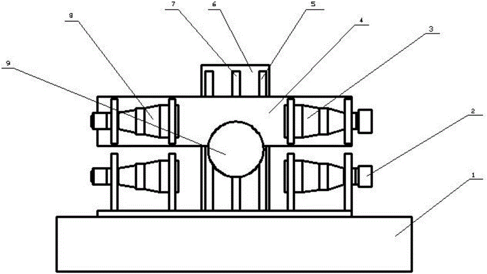
The invention relates to a detection method and equipment for oil pipe thread size parameters, which use parallel light sources for illumination, double telecentric lenses, and area array CCD digital cameras to collect the upper and lower cross-sectional images of oil pipe threads; use image processing software to extract contour sub-pixel edges; calculate the upper and lower cross-sectional images geometric parameters. The detection equipment of the present invention is mainly composed of a base, an image acquisition part, a lifting guide rail mechanism and other components. The image acquisition part consists of a bracket, two parallel LED lighting sources fixed on the bracket, two bi-telecentric lenses, and two area array CCDs. Composed of digital monochrome camera and image acquisition and processing software. The invention adopts a parallel light source and a telecentric lens to ensure that the collected part outline image does not distort with distance within a certain range, has fast measurement speed, and obtains high-precision measurement results.

Description

technical field [0001] The invention belongs to the technical field of mechanical part detection and relates to a method and equipment for acquiring digital images of parts, which can be used for dimension detection of ordinary threads and other parts. Background technique [0002] The oil pipe is a pipeline that transports crude oil and natural gas from the oil and gas layer to the surface after the drilling is completed. It is used in a large amount in the oil field, and the quality of the oil pipe thread directly affects the normal production of the oil field. However, in the current production process of oil pipes, manual methods are commonly used to measure the thread size of oil pipes. Thread gauges and taper gauges are used together with a series of tools for manual inspection. This measurement method has low work efficiency and has a lot of human influence factors. [0003] How to quickly and accurately measure the size of the oil pipe thread space geometry is an urg...

Claims


Application Information

Patent Timeline
IPC IPC(8): G01B11/00G01B11/24G01B11/02G01B11/26G01B11/08G01B11/14
CPCG01B11/00G01B11/02G01B11/08G01B11/14G01B11/2425G01B11/26
Inventor 雷杰牛海军米桂花
Owner XIAN JIECHUANG MEASUREMENT & CONTROL TECH CO LTD
Features
  • R&D
  • Intellectual Property
  • Life Sciences
  • Materials
  • Tech Scout
  • Unparalleled Data Quality
  • Higher Quality Content
  • 60% Fewer Hallucinations
Learn More