A Compact and Electrically Adjustable Balanced Bandpass Filter
A balanced band and compact technology, applied in waveguide devices, circuits, resonators, etc., can solve the problems of non-adjustable bandwidth, non-adjustable bandwidth, limited performance, etc., and achieve the effect of reducing processing difficulty and good common mode suppression performance
- Summary
- Abstract
- Description
- Claims
- Application Information
AI Technical Summary
Problems solved by technology
Method used
Image
Examples
Embodiment 1
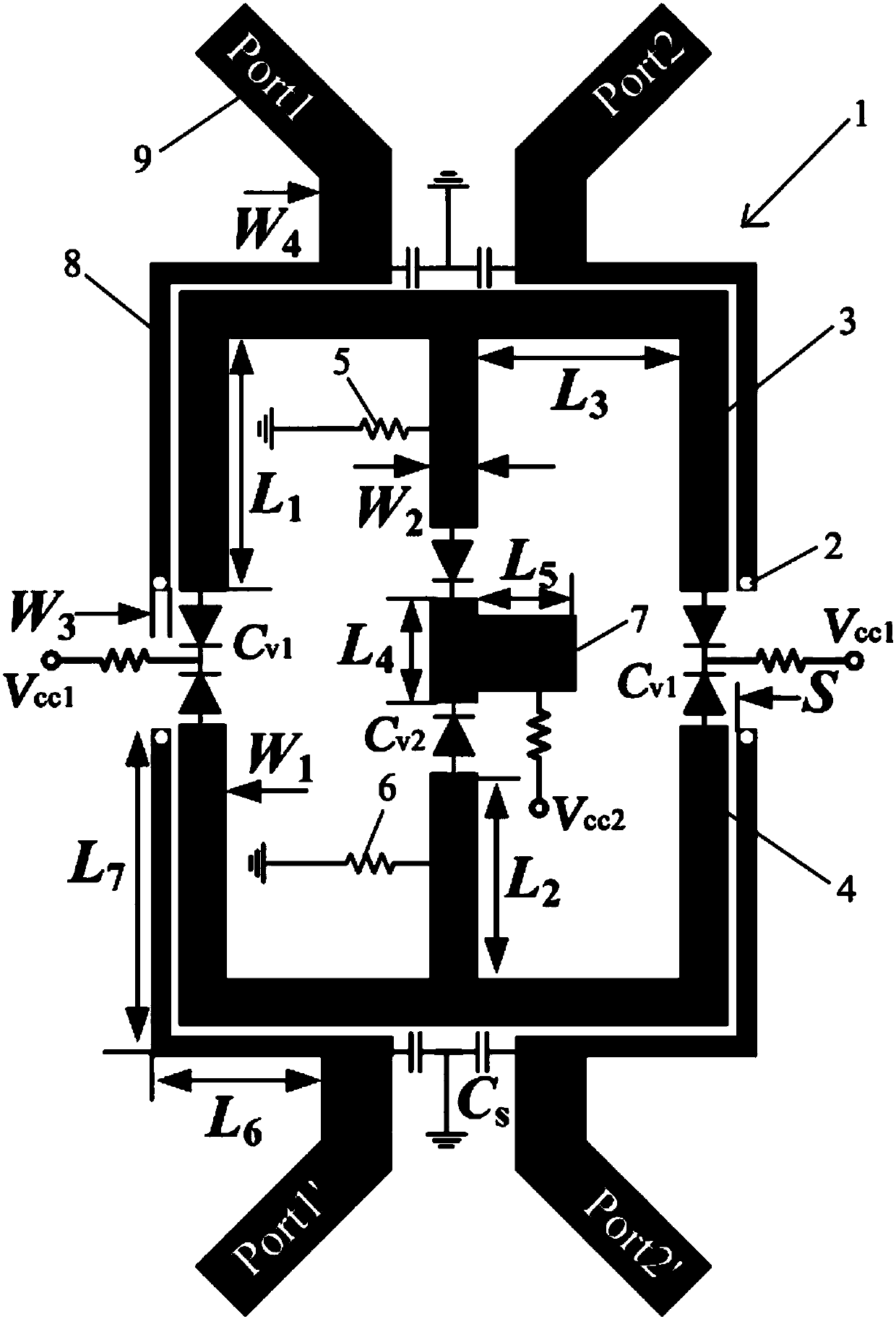
[0042] Such as figure 1 As shown, the balanced bandpass filter of this embodiment includes an upper layer microstrip line structure 1, a middle layer dielectric substrate (not shown in the figure), a lower layer ground metal patch (not shown in the figure) and metal vias 2. The metal through hole 2 runs through the microstrip line structure 1, the dielectric substrate 2 and the grounded metal patch in sequence, so that the microstrip line structure 1 and the grounded metal patch are connected through the dielectric substrate, and the microstrip line structure 1 Includes a multimode resonator and two pairs of input / output feed lines;
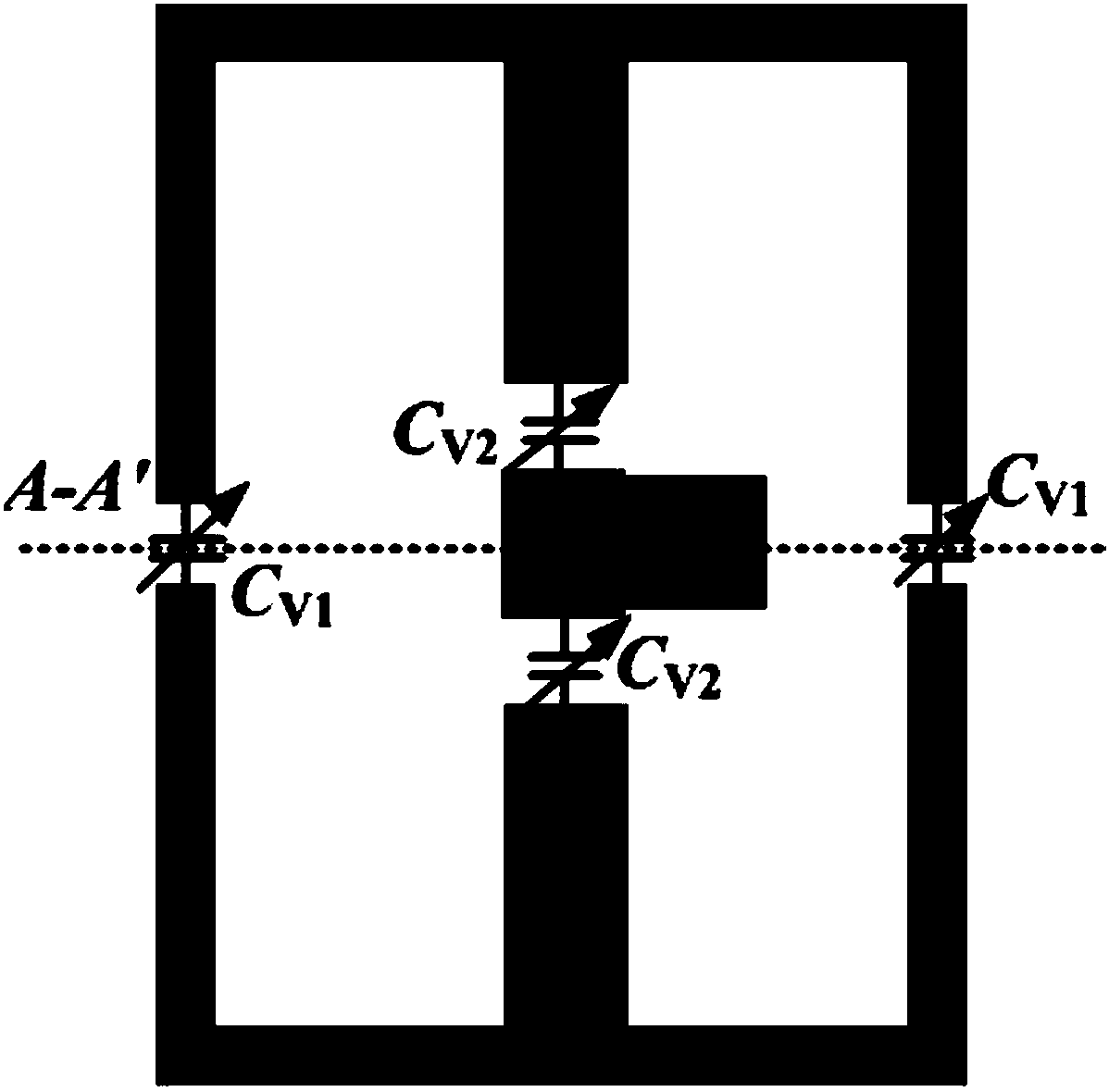
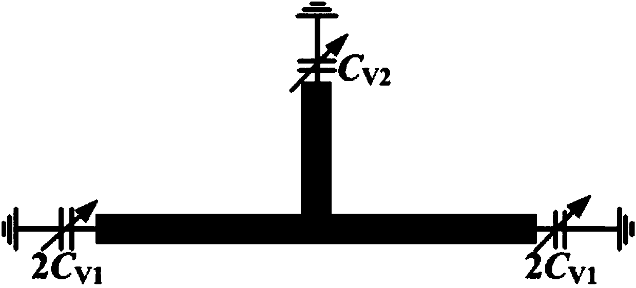
[0043] The multimode resonator as figure 2 As shown, it includes a first microstrip line 3 and a second microstrip line 4 that are symmetrical up and down. Both the first microstrip line 3 and the second microstrip line 4 are E-shaped. The strip stub line and the central microstrip stub line face downward, the microstrip stub line on both side...
Embodiment 2
[0053] A compact electrically adjustable balanced bandpass filter structure such as figure 1 As shown, the electromagnetic simulation software used in this embodiment is Advanced Design System (ADS). The compact electrically adjustable balanced bandpass filter is selected and processed on a dielectric substrate with a dielectric constant of 2.55, a thickness of 0.8mm, and a loss tangent of 0.0029. figure 1The specific physical dimensions are shown in Table 1 below. The fixed capacitor C s =1.8pF, the RF choke coil and the bias resistor are all selected with a resistance value of 100kΩ, and the varactor diode C v1 Select the varactor diode of SMV1405-074 type, and the varactor diode C v2 Select the varactor diode of model SMV1234-079 for use.
[0054]
[0055] Table 1 Dimensions of compact electrically adjustable balanced bandpass filter
[0056] Figure 11 ~ Figure 13 are compact tunable balanced bandpass filters and simulation curve. The horizontal axis of the tr...
PUM
 Abstract
Description
Claims
Application Information
 - R&D
- Intellectual Property
- Life Sciences
- Materials
- Tech Scout
- Unparalleled Data Quality
- Higher Quality Content
- 60% Fewer Hallucinations
Browse by: Latest US Patents, China's latest patents, Technical Efficacy Thesaurus, Application Domain, Technology Topic, Popular Technical Reports.
© 2025 PatSnap. All rights reserved.Legal|Privacy policy|Modern Slavery Act Transparency Statement|Sitemap|About US| Contact US: help@patsnap.com


