Broadband double-ridged horn antenna

A ridge horn and broadband technology, applied in the field of antennas, can solve the problems of complex feeding structure, split lobes and gain drop, and achieve the effects of simplifying complexity, avoiding split lobes and gain drop, and reducing processing costs

Active Publication Date: 2016-06-29
XIDIAN UNIV
View PDF4 Cites 24 Cited by
  • Summary
  • Abstract
  • Description
  • Claims
  • Application Information

AI Technical Summary

Problems solved by technology

[0006] The purpose of the present invention is to overcome the defects in the above-mentioned prior art, and propose a broadband double-ridge horn antenna, which is used to solve the complex feeding structure of the existing broadband double-ridge horn antenna by simplifying the feeding structure and improving the structural form of the ridge line. and technical problems with lobes and gain drop at high frequencies

Method used


Image

  • Broadband double-ridged horn antenna
  • Broadband double-ridged horn antenna
  • Broadband double-ridged horn antenna

Examples


Embodiment 1

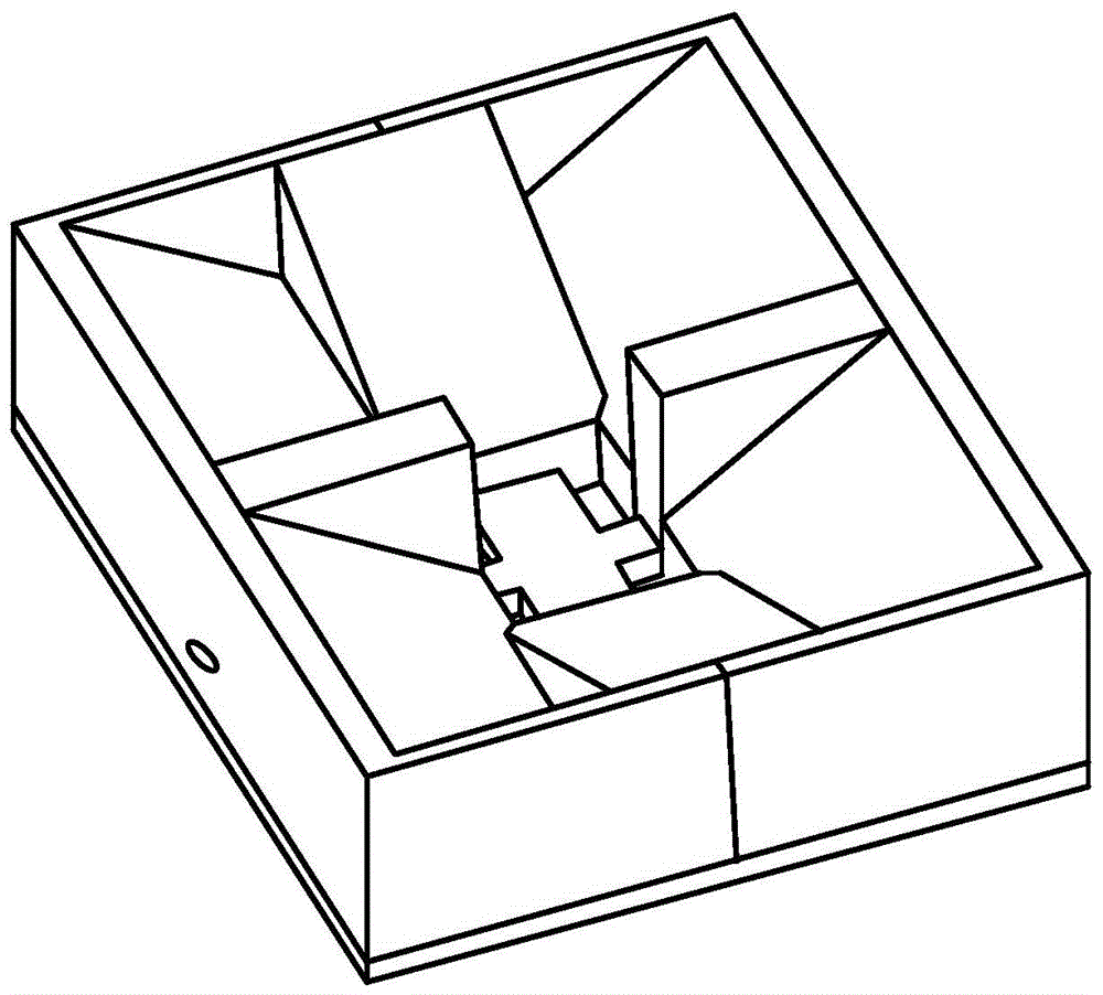
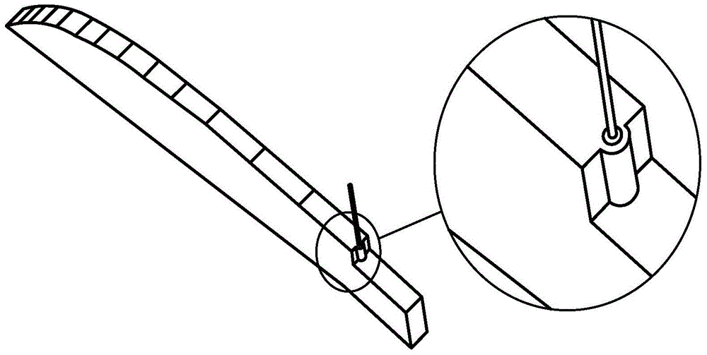
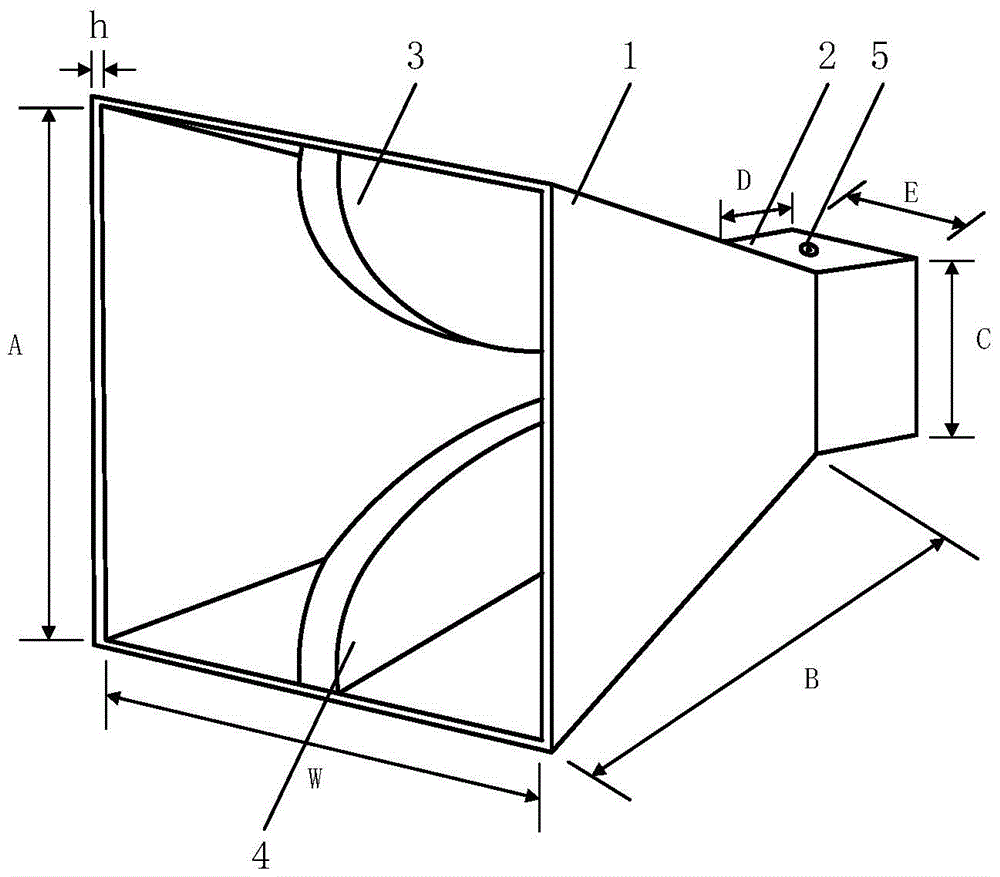
[0028] refer to image 3 , a broadband double-ridge horn antenna, including a horn housing 1, a rectangular waveguide section 2, an upper ridge 3, a lower ridge 4 and a coaxial feeder 5. The horn case 1 is a rectangular cone structure, and its end is connected to the opening of the rectangular waveguide section 2 by welding; the upper ridge 3 and the lower ridge 4 adopt the same structure, and are respectively fixed on the upper side plate and the lower side plate of the horn case 1 by screws. On the inner wall, the outer core of the coaxial feeder 5 connects with the outer wall of the rectangular waveguide section 2 , and the inner core passes through the upper wall of the rectangular waveguide section 2 and the through hole in the upper ridge 3 to connect with the lower ridge 4 .

[0029]The speaker shell 1 is made of light metal material. In this embodiment, aluminum plate is used. Its structure has a rectangular pyramid structure composed of left and right side plates and ...

Embodiment 2

[0036] Embodiment 2 has the same structure as Embodiment 1, only the following parameters are modified: the width dimension J of the ridge is 6mm, the outer dimension C of the rectangular waveguide section 2 is 20mm, the outer dimension D is 10mm, and the outer dimension E is 20mm , the caliber width dimension W of the horn housing 1 is 80mm, the caliber height dimension A is 65mm, and the axial length dimension B is 78mm.

Embodiment 3

[0038] Embodiment 2 has the same structure as Embodiment 1, and only the following parameters are modified: the width dimension J of the ridge is 8.5mm, the outer shape height dimension C of the rectangular waveguide section 2 is 24mm, the outer shape length dimension D is 14mm, and the outer shape width dimension E is 24mm, the caliber width dimension W of the horn housing 1 is 95mm, the caliber height dimension A is 75mm, and the axial length dimension B is 85mm.

[0039] Below in conjunction with simulation result, technical effect of the present invention is further described:

[0040] 1. Simulation content

[0041] The simulation software HFSS is used to model and simulate the antenna structure described in Embodiment 1 above. Such as Figure 6 Embodiment 1 of the present invention is in 2~18GHz VSWR simulation graph; As Figure 7 Embodiment 1 of the present invention is in 2~18GHz gain simulation graph; As Figure 8 a is the E / H plane simulation direction diagram of ...


PUM


Abstract

The invention provides a broadband double-ridged horn antenna for solving the technical problems of complex structure, lobe splitting in high frequencies and gain decline of the existing broadband double-ridged horn antenna. The broadband double-ridged horn antenna comprises a horn shell (1), a rectangular waveguide section (2), an upper ridge (3), a lower ridge (4) and a coaxial feeder line (5), wherein the rectangular waveguide section (2) adopts a cubic structure with a cavity; the ridge lines of the upper ridge (3) and the lower ridge (4) are both formed by linear sections and curved sections, wherein the curved sections adopt cubic bezier curves, and the coordinate values of the endpoint control points at the tail end of the curve are greater than that of the endpoints at the tail end; the two ridges (3, 4) are fixed on the inner walls of the upper side plate and the lower side plate of the horn shell (1); and the coaxial feeder line (5) passes through the top end of the rectangular waveguide section (2) to be connected with the upper ridge (3) and the lower ridge (4). The broadband double-ridged horn antenna has a simple feed structure, and can maintain sable directional diagram characteristics within a broadband range, so that the horn antenna is suitable for being used as the feed source for a standard measurement antenna and a reflector.

Description

technical field [0001] The invention belongs to the technical field of antennas, and relates to a broadband double-ridge horn antenna, in particular to a double-ridge horn antenna with simplified feeding structure and improved ridge line structure, which is suitable as a feed source for standard measurement antennas and reflectors. Background technique [0002] With the continuous development of wireless communication technology, people's requirements for antenna performance are getting higher and higher, and traditional narrowband antennas can no longer meet people's needs. In many fields, such as television, FM broadcasting, telemetry technology, aerospace and satellite communications, etc., high-quality transmission of language, text, data, images and even video information is required. With the continuous expansion of channel capacity and continuous improvement of transmission rate, the original spectrum resources become very crowded. Therefore, UWB antenna technology h...

Claims


Application Information

Patent Timeline
Patent Type & Authority Applications(China)
IPC IPC(8): H01Q13/02
CPCH01Q13/0275
Inventor 刘英岳震震章玉涛龚书喜
Owner XIDIAN UNIV
Why Eureka
Try Eureka